Difference between revisions of "Contrib:KeesWouters/plasticity/solidbeam"
From CAELinuxWiki
Keeswouters (Talk | contribs) (→'''Geometry and mesh of the solid beam''') |
Keeswouters (Talk | contribs) m (→'''Geometry and mesh of the solid beam''') |
||
| Line 11: | Line 11: | ||
Fbot and Ftop are the bottom and top surfaces.<br/> | Fbot and Ftop are the bottom and top surfaces.<br/> | ||
Lx and Ly are the edges along the x and y axes. | Lx and Ly are the edges along the x and y axes. | ||
| + | |||
| + | |||
| + | : [[image:kw_sigma_epsilon.png]] | ||
Revision as of 16:14, 30 April 2010
Solid beam under plastic deformation
This contribution is based on . This contribution has been created because of some incompatibilities between version CA10.X.Y and earlier versions. For detailed description of the calculation sequence look here.
Geometry and mesh of the solid beam
Using a straight solid beam is easy for analysis of the stresses and strains.
-
 *
* 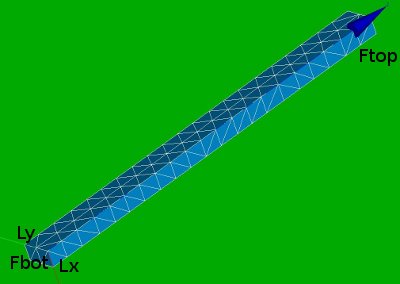


Fbot and Ftop are the bottom and top surfaces.
Lx and Ly are the edges along the x and y axes.