Contrib:KeesWouters/plasticity/solidbeam
Contents
Solid beam under plastic deformation
This contribution has been created because of some incompatibilities between version CA10.X.Y and earlier versions. For detailed description of the calculation sequence look here.
Geometry and mesh of the solid beam
Using a straight solid beam is easy for analysis of the stresses and strains.
-
 *
* 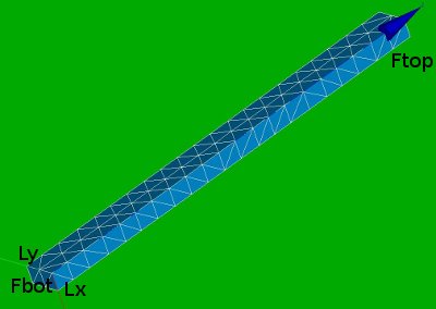


Fbot and Ftop are the bottom and top surfaces.
Lx and Ly are the edges along the x and y axes.
NRbot (Nodal Reaction at the bottom plane) and NFtop (Nodal Force at the top plane) are two nodes to determine the displacement and reaction force of the construction.
Non linear material behaviour
The non linear material behaviour is defined by the sigma epsilon curve. The CA commands for this relation are given by DEFI_FONCTION and DEFI_MATERIAU. The curve that has been used in this calculation is depicted below.
Sigma_eps = DEFI_FONCTION(NOM_PARA='EPSI',
                          VALE=(0.0016,	330,
                                0.0032,	350,
                                0.0064,	367,
                                0.0128,	387,
                                0.0200,	401,
                                0.0270,	410,
                                0.0400,	420,
                                0.0700,	437,
                                0.1000,	450,
                                0.1500,	473,
                                0.2000,	490,
                                0.3000,	510,),
                     INTERPOL='LIN',PROL_DROITE='LINEAIRE',PROL_GAUCHE='EXCLU',);
#define plastic behaviour of steel by Sigma_eps
steel=DEFI_MATERIAU(ELAS=_F(E=2.1e5,NU=0.27,),
                    TRACTION=_F(SIGM=Sigma_eps,),);

Note that the origin need not to be specified for the sigma epsilon in the DEFI_FONCTION.
The boundary conditions and the loads
For the boundary conditions we choose to fix:
- the bottom plane in axial (z) direction,
- the edge along the x axis in y direction and
- the edge along the y axis in x direction
LoadFix=AFFE_CHAR_MECA(MODELE=pmode,
                   FACE_IMPO=(_F(GROUP_MA='Fbot',DZ=0.0,),),
                   DDL_IMPO=(_F(GROUP_MA='Lx',DY=0.0),
                             _F(GROUP_MA='Ly',DX=0.0),),);
For the load we apply an axial force on the top plane. The force is gradually increased to its maximum value, kept constant and reduced to zero again. This is performed by the multiplification function ramp in the load command.
# LoadPres will vary in the nonlinear calculation determined by the 'time' and  'ramp' function
# number of 'time' steps tsteps
# ramp increases during:
# 1.2 s: from 0.0 to 1.0,
# 0.1 s: constant at 1.0
# 1.4 s: from 1.0 down to -1.0
dt = 0.10
t0 = 0.00
t1 = 1.20
t2 = t1+dt
t3 = t2+2*t1
tsteps = int(t3*10)
disp = 0.0750
LoadPres=AFFE_CHAR_MECA(MODELE=pmode,
                   FACE_IMPO=(_F(GROUP_MA='Ftop',DZ=disp,),),);
ramp=DEFI_FONCTION(NOM_PARA='INST',
                  VALE=(t0,0.00,
                        t1,1.00,
                        t2,1.00,
                        t3,0.30,),
                  INFO=2,TITRE='ramp',);
time=DEFI_LIST_REEL(DEBUT=0.0,
                   INTERVALLE=_F(JUSQU_A=t3,NOMBRE=tsteps,),
                   INFO=2,TITRE='time',);
deflist = DEFI_LIST_INST(DEFI_LIST=_F(METHODE ='AUTO',
                                     LIST_INST = time,
                                     PAS_MINI = 0.0005),)
Presul=STAT_NON_LINE(MODELE=pmode,
                    CHAM_MATER=matprops,
                    EXCIT=(_F(CHARGE=LoadFix,),
                           _F(CHARGE=LoadPres,FONC_MULT=ramp,),),
                    COMP_INCR=_F(RELATION='VMIS_ISOT_TRAC',
                                 DEFORMATION='SIMO_MIEHE',
                                 TOUT='OUI',),
                    INCREMENT=_F(LIST_INST= deflist,), #time,
                    NEWTON=_F(REAC_INCR=1,
                              MATRICE='TANGENTE',
                              REAC_ITER=1,),
                    CONVERGENCE=_F(ITER_GLOB_MAXI=20,),
                    ARCHIVAGE=_F(PAS_ARCH=1,),);
For comparison the linear calculation is applied as well:
LinRes=MECA_STATIQUE(MODELE=pmode,
                    CHAM_MATER=matprops,
                    EXCIT=(_F(CHARGE=LoadFix,),
                           _F(CHARGE=LoadPres,),),);
The results
Intermezzo - the results of the linear calculation
| commands to determine stresses and strains | remarks on the commands |
|---|---|
POURSUITE(); |
first perform a calculation |
LinRes=CALC_ELEM(reuse = LinRes,
                 OPTION=('SIGM_ELNO_DEPL','EQUI_ELNO_SIGM','SIEF_ELNO_ELGA',
                         'EPSI_ELNO_DEPL','EQUI_ELNO_EPSI',),
                 RESULTAT=LinRes,);
|
calculate element results SIGM_ELNO_DEPL --> local stresses SIab EQUI_ELNO_SIGM --> equivalent stresses VMIS,TRESCA,.. SIEF_ELNO_ELGA --> equivalent stresses at gauss points EPSI_ELNO_DEPL --> local strains EPSab EQUI_ELNO_EPSI --> equivalent strains |
LinRes=CALC_NO(reuse =LinRes,
               RESULTAT=LinRes,
               OPTION= ('SIEF_NOEU_ELGA','SIGM_NOEU_DEPL','EQUI_NOEU_SIGM',
                        'FORC_NODA','REAC_NODA',),);
               OPTION= ('SIEF_NOEU_ELGA','SIGM_NOEU_DEPL','EQUI_NOEU_SIGM',
                        'EPSI_NOEU_DEPL','EQUI_NOEU_EPSI',
                        'FORC_NODA','REAC_NODA',),);
|
calculate nodal equivalents and reaction forces
SIEF_ELNO_ELGA --> SIEF_NOEU_ELGA --> local stresses at gauss points
SIGM_ELNO_DEPL --> SIGM_NOEU_DEPL --> local stresses SIab
EQUI_ELNO_SIGM --> EQUI_NOEU_SIGM --> equivalent stresses VMIS, TRESCA, ...
EPSI_ELNO_DEPL --> EPSI_NOEU_DEPL --> local strains EQUI_ELNO_EPSI --> EQUI_NOEU_EPSI --> equivalent strains FORC_NODA --> nodal forces REAC_NODA --> reaction forces |
IMPR_RESU(FORMAT='MED',
         UNITE=80,
         RESU=(_F(MAILLAGE=pmesh,
                  RESULTAT=LinRes,
                  NOM_CHAM='DEPL',
                  NOM_CMP=('DX','DY','DZ',),),
               _F(MAILLAGE=pmesh,
                  RESULTAT=LinRes,
                  NOM_CHAM='SIEF_NOEU_ELGA',),
                  #NOM_CMP=('SIXX','SIYY','SIZZ',),),
               _F(MAILLAGE=pmesh,
                  RESULTAT=LinRes,
                  NOM_CHAM='SIGM_NOEU_DEPL',),
               _F(MAILLAGE=pmesh,
                  RESULTAT=LinRes,
                  NOM_CHAM='EQUI_ELNO_SIGM',),
               _F(MAILLAGE=pmesh,
                  RESULTAT=LinRes,
                  NOM_CHAM='EQUI_NOEU_SIGM',),),);
|
write fields to med file,
possible choises of the components of the field (NOM_CMP):
NOM_CHAM='DEPL' -->
NOM_CMP=('DX','DY','DZ',)
NOM_CHAM='SIEF_NOEU_ELGA' -->
  NOM_CMP=('SIXX','SIYY','SIZZ','SIXY','SIXZ','SIYZ')
NOM_CHAM='SIGM_NOEU_DEPL' -->
  NOM_CMP=('SIXX','SIYY','SIZZ','SIXY','SIXZ','SIYZ')
NOM_CHAM='EQUI_ELNO_SIGM' -->
  NOM_CMP=('VMIS','TRESCA','PRIN_1','PRIN_2','PRIN_3','VMIS_SG','TRSIG')
|
IMPR_RESU(FORMAT='MED',
         UNITE=80,
         RESU=(_F(RESULTAT=LinRes,
                  NOM_CHAM='EPSI_ELNO_DEPL',),
               _F(RESULTAT=LinRes,
                  NOM_CHAM='EQUI_ELNO_EPSI',),),);
|
write strains to med file NOM_CHAM='EPSI_ELNO_DEPL' -->
NOM_CMP=('EPXX','EPYY','EPZZ','EPXY','EPXZ','EPYZ')
NOM_CHAM='EQUI_ELNO_EPSI' -->
NOM_CMP=('INVA_2','PRIN_1','PRIN_2','PRIN_3','INVA_2SG')
|
pmesh=DEFI_GROUP(reuse =pmesh,
                MAILLAGE=pmesh,
                CREA_GROUP_NO=_F(NOM='Nreac',GROUP_MA='Fbot',),);
pmesh=DEFI_GROUP(reuse =pmesh,
                MAILLAGE=pmesh,
                CREA_GROUP_NO=_F(NOM='Nforce',GROUP_MA='Ftop',),);
|
define groups of nodes from geometrical entities 'Ftop' and 'Fbot' |
TB_nodf=POST_RELEVE_T(ACTION=(_F(OPERATION='EXTRACTION',
                               INTITULE='displacements',
                               RESULTAT=LinRes,
                               NOM_CHAM='DEPL',
                               TOUT_ORDRE='OUI',
                               GROUP_NO='Nforce',
                               RESULTANTE=('DX','DY','DZ',),
                               MOYE_NOEUD='NON',),
                            _F(OPERATION='EXTRACTION',
                               INTITULE='ReactionForces',
                               RESULTAT=LinRes,
                               NOM_CHAM='REAC_NODA',
                               TOUT_ORDRE='OUI',
                               GROUP_NO='Nreac',
                               RESULTANTE=('DX','DY','DZ',),
                               MOYE_NOEUD='NON',),
                            _F(OPERATION='EXTRACTION',
                               INTITULE='NodalForces',
                               RESULTAT=LinRes,
                               NOM_CHAM='FORC_NODA',
                               PRECISION=0.000001,
                               GROUP_NO='Nreac',
                               RESULTANTE=('DX','DY','DZ',),),),
                            TITRE='[Reaction] Nodal Forces',);
|
define fields to write to the table TB_nodf |
IMPR_TABLE(TABLE=TB_nodf,
        FORMAT='TABLEAU',
        UNITE=26,
        SEPARATEUR=' * ',
        TITRE='displacements at nodes on group Nforce',);
|
write table TB_nodf to file |
| default values of CALC_ELEM | possible fields to write to file |
|---|---|
default values for
LinRes=CALC_ELEM(reuse=LinRes,RESULTAT=LinRes) -->
LinRes=CALC_ELEM(reuse = LinRes,
INFO=1,
CRITERE='RELATIF',
OPTION='LinRes=CALC_ELEM(reuse = LinRes,
INFO=1,
CRITERE='RELATIF',
OPTION='SIEF_ELNO_ELGA',
TYPE_OPTION='TOUTES',
SOLVEUR=_F(RENUM='METIS',
STOP_SINGULIER='OUI',METHODE='MULT_FRONT',NPREC=8),
PRECISION=1.0E-06,
RESULTAT=LinRes,);
|
now you can write
    NOM_CHAM='DEPL' and
    NOM_CHAMP='SIEF_ELNO_ELGA'
to a med file.
|
-
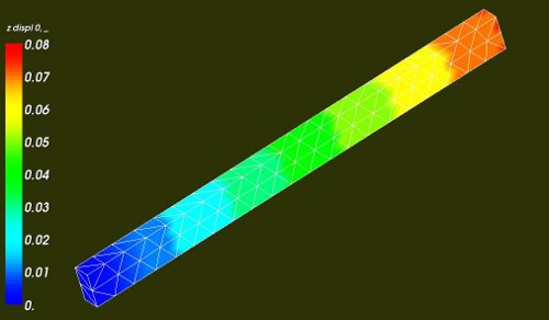
- Axial displacement of the beam, maximum displacement at the top 0.075 [mm].

-
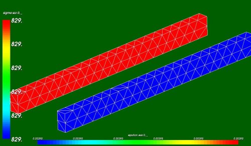
- Elastic axial stresses sigma_zz (red beam, value 829 [MPa]) and strains eps_zz (blue beam, 3.95 [mm/m])

Theoretical verification:
- length of the beam: 19 mm
- cross section: 0.8*1.5 = 1.2 mm2
- Young's module: E = 2.1e5 MPa
- In the linear case, this yields a stress sigma and strain epsilon:
- epsilon e_zz = dz/Lz = 0.075/19 = 0.00395 ~ 0.004 [-]
- sigma = e_zz*E = 829 MPa
- On the top 15 nodes the displacements and reaction forces are:
- dz = 1.12500E+00 [mm] --> 0.075 mm at each node (that is correct)
- Rz = -9.94737E+02 [N] --> pressure is Rz/A = -9.94737E+02/1.2 = 829 MPa (that is correct as well).
The results of the non linear calculation
The load is now a varying displacement of the top plane 'Ftop'. The maximum displacement is 0.075 mm. The scaling factor for this displacement is ramping from 0 to 1, remaining at 1 for one time step and decreasing to -1, see blue curve in the picture below.

- displacement of to the top plane 'Ftop' (left scale - blue)
- nodal force of the bottom plane 'Fbot' (right scale - red)
- plastic deformation EPSP in z direction (left scale * 10 - green-black)
- total deformation EPSI in z direction (left scale * 10 - green-black-dashed)
- the sign of the quantities may have been changed to obtain graphs that can easier be understood.

axial stress SIZZ in the beam (light blue beam, value 400 MPa) axial (plastic????) strain EPS_PL_ZZ in the beam (green beam, value 0.002 [-])
Theoretical the total strain is 0.0039. According to the yield curve the corresponding stress is than ~360 MPa (****so the result SIZZ is overestimating, but I am not really sure of the exact value of the calculated stress****). The maximum linear strain is sigma_max/E = 360/210000 ~ 0.0017, hence the plastic stress is 0.0039-0.0017 ~ 0.0022. This is in accordance with the values in the curves above.
The commands for the non linear calculation
The commands:
| commands to determine stresses and strains | remarks on the commands |
|---|---|
POURSUITE(); |
first perform a calculation |
Presul=CALC_ELEM(reuse = Presul,
                INFO=2,
                TYPE_OPTION='TOUTES',
                OPTION=('SIEF_ELNO_ELGA','EPSI_ELNO_DEPL','EPSP_ELNO',
                        'EQUI_ELNO_SIGM','EQUI_ELNO_EPSI','EPSP_ELGA',
                        'EPSI_ELGA_DEPL','EPSG_ELNO_DEPL','EPSG_ELGA_DEPL'),
                RESULTAT=Presul,);
# calculate nodal equivalents and reaction forces
Presul=CALC_NO(reuse =Presul,
            RESULTAT=Presul,
            OPTION= ('SIEF_NOEU_ELGA','FORC_NODA','REAC_NODA',),);
|
determine stresses and strains on element and node level |
# write Results to MED file
IMPR_RESU(FORMAT='MED',
         UNITE=80,
         RESU=(_F(RESULTAT=Presul,
                  NOM_CHAM='DEPL',),
               _F(RESULTAT=Presul,
                  NOM_CHAM='SIEF_NOEU_ELGA',),
               _F(RESULTAT=Presul,
                  NOM_CHAM='EPSI_ELNO_DEPL',),
               _F(RESULTAT=Presul,
                  NOM_CHAM='EPSP_ELNO'),),);
|
write to file the following fields:
|
# create nodal groups from mesh groups for use in table
pmesh=DEFI_GROUP(reuse =pmesh,
                MAILLAGE=pmesh,
                CREA_GROUP_NO=_F(NOM='Nforce',GROUP_MA='Ftop',),);
pmesh=DEFI_GROUP(reuse =pmesh,
                MAILLAGE=pmesh,
                CREA_GROUP_NO=_F(NOM='Nreac',GROUP_MA='Fbot',),);
|
define nodal groups Nforce and Nreac based on the geometrical quantities Ftop and Fbot. |
TB_nodf=POST_RELEVE_T(ACTION=(_F(OPERATION='EXTRACTION',
                               INTITULE='displacements',
                               RESULTAT=Presul,
                               NOM_CHAM='DEPL',
                               TOUT_ORDRE='OUI',
                               GROUP_NO='Nforce',
                               RESULTANTE=('DX','DY','DZ',),
                               MOYE_NOEUD='NON',),
                            _F(OPERATION='EXTRACTION',
                               INTITULE='displacements',
                               RESULTAT=Presul,
                               NOM_CHAM='EPSP_ELNO',
                               TOUT_ORDRE='OUI',
                               TOUT_CMP='OUI',
                               GROUP_NO='NRbot',),
                            _F(OPERATION='EXTRACTION',
                               INTITULE='displacements',
                               RESULTAT=Presul,
                               NOM_CHAM='EPSI_ELNO_DEPL',
                               TOUT_ORDRE='OUI',
                               TOUT_CMP='OUI',
                               GROUP_NO='NRbot',),
                            _F(OPERATION='EXTRACTION',
                               INTITULE='ReactionForces',
                               RESULTAT=Presul,
                               NOM_CHAM='REAC_NODA',
                               TOUT_ORDRE='OUI',
                               GROUP_NO='Nreac',
                               RESULTANTE=('DX','DY','DZ',),
                               MOYE_NOEUD='NON',),
                            _F(OPERATION='EXTRACTION',
                               INTITULE='NodalForces',
                               RESULTAT=Presul,
                               NOM_CHAM='FORC_NODA',
                               PRECISION=0.000001,
                               GROUP_NO='Nreac',
                               RESULTANTE=('DX','DY','DZ',),),),
                            TITRE='[Reaction] Nodal Forces',);
|
|
IMPR_TABLE(TABLE=TB_nodf,
        FORMAT='TABLEAU',
        UNITE=26,
        SEPARATEUR=' * ',
        TITRE='displacements at nodes on group Nforce',);
FIN(); |
Small summary:
- The key word SIGM_XXXX_DEPL cannot be used in non linear calculations. It determines the stresses SIGM based on the displacements DEPL. This assumes a linear relation. Use eg SIEF_NOEU_ELGA instead; see ELEM_CALC key words.
- The key word EPSX_XXXX_DEPL can be used in non linear calculations since the strain indeed only depends on the displacements (in short: eps = dxj - dxi). It determines the total strains EPSX.
- In the CALC_ELEM command I used as much key words as possible that are valid for this calculation. You can extend CALC_NO to reflect this choice, ie. CALC_ELEM(.....XXXX_ELNO_YYYY,....) --> CALC_NO(....XXXX_NOEU_YYYY,....).
- .....
Download input files
- The file gm_beam4.py defines geometry and mesh of the beam. After loading the script (cntrl T) into Salome, click refresh in the tree and save the meshbox mesh as meshbox.med mesh file (right click on mesh in the object browser --> Export as MED).
- The commands are split into 3 parts :
- calc_lin_nonlin.comm to compute the mechanics: both linear and non linear material behaviour is given (run first)
- post_lin.comm performs the post processing of the linear result (ResLin) and
- post_nonlin.comm performs -no suprise- the post processing of the non linear result (Presul).
- the corresponding ASTK and export files are named accordingly.
- The post processing files use poursuite() to continue from the calculation performed in the first file. This, among others, means that the base file is an input for the post processing for ASTK. The use of poursuite() with separate post processing files reduces the time to do 'tests' to find valid key words, since the mechanical calculations does not need to be performed over and over again.
- The output of the post processing are med and text files. The text file is used to produce the graphs above.
- The postprocessing files should now end with _OKE. If this is not true for you, please let me know. The main calculation still yields a warning; I will try to get ride of that one.
So far
Any comments welcome
may 2010
Kees