Contrib:KeesWouters/dynamicload
Contents
Dynamic analysis of an axial loaded cylinder
[under construction .... not finished yet ...]
To start with, this contribution mainly focuses on the use of Salome and Code Aster, not on the results and the mechanical justifications of the code that has been used. So no guarantee that the results will be correct up to the fifth decimal place, which they are not. I do hope though that this information is useful. For me it has been, because I had to think about some commands and look through the documentation and learn from that. In case of mistakes, errors or remarks, please notify me, or better, you are invited to correct or edit them yourself. Enjoy.
[As usual, the files that define the geometry, mesh and command files can be found at the end of this contribution.]
Geometry of the construction
The geometry is based on this contribution: [[]]. Only the mesh is much coarser to limit calculation time.
Boundary condition and load
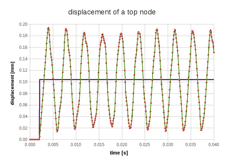
Also the boundary conditions are the same as [here], as is the load. The load is an axial force on the top edge of the cylinder. A scaling factor is applied by the MULT_FONCT command in the []. This scaling factor is zero for the first 100 ms, and goes to unity within a very small time scale, ie. small compared to the resonance frequencies of the axial modes of the cylinder. The scale factor remains unity until the end of the calculation at 300 ms.
Detailed commands of the applied load
The AFFE_CHAR_MECA defines the boundary conditions at the bottom of the cylinder: all dofs are restricted. At the top an axial force is applied with a total force of 5500 N, devided over the circumference of the cylinder.
# define BC and loads
# geometry of cylinder for applying loads
th    = 0.10        # [mm] thickness of shell
dcyl  = 4.00        # [mm] diameter of cylinder
pie   = math.pi
Lcyl  = pie*dcyl    # [mm] circumference of the cylinder
Fax   = 5500.0      # [N]  total axial force
clamp=AFFE_CHAR_MECA(MODELE=modelc,
                      DDL_IMPO=(_F(GROUP_MA=('Cbot'),
                                  DX=0.0,
                                  DY=0.0,
                                  DZ=0.0,
                                  DRX=0.0,
                                  DRY=0.0,
                                  DRZ=0.0,),
                                 _F(GROUP_MA=('Ctop'),
                                  DX=0.0,
                                  DY=0.0,
                                  DRX=0.0,
                                  DRY=0.0,
                                  DRZ=0.0,),),
                      FORCE_ARETE=_F(GROUP_MA='Ctop',FZ=+Fax/Lcyl,),);
......
A time step is defined by the DEFI_LIST_REEL command. The scaling function castle is defined by the DEFI_FONCTION command. In total tsteps (200) output times will be generated.
# The load will be applied in steps defined by a 'time' function and
# multiplification factor on the load.
tsteps = 200
to     = 0.000
tc     = 0.005
t1     = (1+1e-5)*tc
te     = 0.020
time=DEFI_LIST_REEL(DEBUT=0.0,
                  INTERVALLE=_F(JUSQU_A=te,NOMBRE=tsteps,),
                  INFO=2,TITRE='time',);
castle=DEFI_FONCTION(NOM_PARA='INST',
                 VALE=(to,  0.00,
                       tc,  0.00,
                       t1 , 1.00,
                       te,  1.00,),
                 INFO=2,TITRE='castle',);
Defining the solution process
We define the dynamic load and solution process by the DYNA_LINE_TRAN command:
Rdyn = DYNA_LINE_TRAN(MODELE=modelc,
                     CHAM_MATER= matprops,
                     CARA_ELEM = shellch,
                     MATR_MASS = Mmasse,
                     MATR_RIGI = Mstiff,
                     MATR_AMOR = Mdampg,
                     NEWMARK   = _F(ALPHA = 0.25,DELTA = 0.5,),
                     EXCIT     = _F(CHARGE = clamp,FONC_MULT = castle,),
                     INCREMENT = _F(LIST_INST=time,),);
Here the standard parameters are given: MODELE for the defined model, CHAM_MATER for the material properties, and since we use shell elements (coque_3d) also the CARA_ELEM is required. For the numerical integration we need the stiffness, mass and damping matrices MATR_RIGI, MATR_MASS and MATR_AMOR. The integration method is defined: in this case NEWMARK with default alpha and delta parameter. The excitation has been discussed previously: the structure clamp and the scalin g function castle. Finally the integration time is defined in INCREMENT.
Result for post processing
Since we use a quad9 element (coque_3d), that cannot be displayed in Salome, we have to project the results to the quad8 mesh suitable for Salome and write the results to file.
SALmodes=PROJ_CHAMP(RESULTAT=Rdyn,
                   MODELE_1=modelc,
                   MODELE_2=modinit,);
IMPR_RESU(FORMAT='MED',
         UNITE=21,
         RESU=_F(MAILLAGE=meshinit,
                 RESULTAT=SALmodes,
                 NOM_CHAM='DEPL',),);
Writing displacements of a single node
Since we would like to see the time responce of the cylinder, we write the displacements of a single node (node N6) on top of the cylinder to file. This node has already defined in Salome and is part of the med file.
TB_nodf=POST_RELEVE_T(ACTION=(_F(OPERATION='EXTRACTION',
                              INTITULE='displacements',
                              RESULTAT=Rdyn,
                              NOM_CHAM='DEPL',
                              TOUT_ORDRE='OUI',
                              GROUP_NO='N6',
                              RESULTANTE=('DX','DY','DZ',),
                              MOYE_NOEUD='NON',),),
                             TITRE='Displacement top of cylinder',);
#Finally, write the data to a file (define a file in ASTK with file unit 26, in this case).
IMPR_TABLE(TABLE=TB_nodf,
       FORMAT='TABLEAU',
       UNITE=26,
       SEPARATEUR=' * ',
       TITRE='displacements at nodes on group N6',);
