Difference between revisions of "Contrib:KeesWouters/beambuckling"
Keeswouters (Talk | contribs) (→'''Critical loads Code-Aster''') |
Keeswouters (Talk | contribs) (→'''Critical loads Code-Aster''') |
||
| Line 33: | Line 33: | ||
==='''Critical loads Code-Aster'''=== | ==='''Critical loads Code-Aster'''=== | ||
Since we applied a displacement on the '''top''' face, we are interested in the corresponding axial force. On this plane, the extracted axial force is -660.4 N, slightly more than the analytic result. | Since we applied a displacement on the '''top''' face, we are interested in the corresponding axial force. On this plane, the extracted axial force is -660.4 N, slightly more than the analytic result. | ||
| + | |||
| + | The nodal forces, reaction forces and displacements of the '''top''' plane can be extracted from the result by defining a table and write them to a file: | ||
| + | TB_nodf=POST_RELEVE_T(ACTION=(_F(OPERATION='EXTRACTION', ...) | ||
| + | IMPR_TABLE(TABLE=TB_nodf,FORMAT='TABLEAU',UNITE=26,SEPARATEUR=' * ', | ||
| + | TITRE='displacements at nodes on group TOP',); | ||
#displacements at nodes on group top | #displacements at nodes on group top | ||
Revision as of 12:06, 19 August 2009
Contents
Buckling behaviour of a beam
To start with, this contribution mainly focuses on the use of Salome and Code Aster, not on the results and the mechanical justifications of the code that has been used. So no garantees that the results will be correct upto the fifth decimal place, which they are not. I do hope though that this information is useful. For me it has been, because I had to think about some commands and look through the documentation and learn from that. In case of mistakes, errors and the like, please notify me, or better, you are invited to correct them yourself. Enjoy.
Critical load according to Euler
The construction is a prismatic beam with diameter 1 and length 50 mm. The material is steel. According to Euler the the critical load with fixed i.e clamped boundary conditions at both ends of the beam is
- Fcr = E*Iss*(pi/(k*L))^2,
- k = 0.5 for clamped boundary conditions
- Youngs' modulus E = 2.1e5 MPa
- poisson ratio nu = 0.28, not needed for the Euler beam
- smallest moment of inertia Iss = pi/64*d^4 = 0.049 mm4
- length of the beam L = 50 mm
- corresponding axial load Fax = Cz*Uz = EA/L * Uz = 3298.7 * 0.2 = 659.7 N
- Fcr = 162.8 N or a ratio of
- ratio = Fcr/Fax = 0.247
This last value is what we are looking for in the buckling analysis with Code-Aster.
Beam with solid elements
-
 *
* 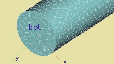


The construction is readily defined in the Geometry module of Salome by Cylinder, radius 0.5 and length 50 mm, at the origin of the coordinate system. The axial direction of the beam coincides with the global z axis. The two axial faces of the beam are denoted by 'bot' and 'top'. The boundary conditions are are dx=dy=dz=0 at the 'bot' and dx=dy=0, dz=-0.2 mm at 'top'.
tbc...
Critical loads Code-Aster
Since we applied a displacement on the top face, we are interested in the corresponding axial force. On this plane, the extracted axial force is -660.4 N, slightly more than the analytic result.
The nodal forces, reaction forces and displacements of the top plane can be extracted from the result by defining a table and write them to a file:
TB_nodf=POST_RELEVE_T(ACTION=(_F(OPERATION='EXTRACTION', ...)
IMPR_TABLE(TABLE=TB_nodf,FORMAT='TABLEAU',UNITE=26,SEPARATEUR=' * ',
           TITRE='displacements at nodes on group TOP',);
#displacements at nodes on group top
#[Reaction] Nodal  Forces
* INTITULE         * RESU     * NOM_CHAM         * NUME_ORDRE   * INST         * DX           * DY           * DZ
* displacements    * result   * DEPL             *            1 *  0.00000E+00 * -7.30250E-19 * -3.47836E-17 * -4.08000E+01
* ReactionForces   * result   * REAC_NODA        *            1 *  0.00000E+00 *  2.83321E-06 *  8.20372E-06 * -6.60449E+02
* NodalForces      * result   * FORC_NODA        *            1 *  0.00000E+00 *  2.83321E-06 *  8.20372E-06 * -6.60449E+02
CALCUL MODAL:  METHODE D'ITERATION SIMULTANEE
                     METHODE DE SORENSEN
NUMERO    CHARGE CRITIQUE    NORME D'ERREUR
   1      -9.72998E-01       3.68322E-09
   2      -9.72990E-01       3.42967E-09
   3      -5.00953E-01       5.82225E-09
   4      -5.00949E-01       6.01805E-09
   5      -2.45979E-01       3.26885E-08
   6      -2.45977E-01       3.10062E-08
NORME D'ERREUR MOYENNE:  0.13775E-07