Difference between revisions of "Contrib:KeesWouters/bc/pythonlist"
Keeswouters (Talk | contribs) m (→''Adding the boundary conditions to the calculation'') |
Keeswouters (Talk | contribs) m (→''Adaption of the code - B usefull '') |
||
| Line 98: | Line 98: | ||
ny = ncoor[ic][1] | ny = ncoor[ic][1] | ||
nz = ncoor[ic][2] | nz = ncoor[ic][2] | ||
| − | icp1 = ic+1 # node numbers are increased by 1 | + | icp1 = ic+1 # node numbers are increased by 1: Salome <--> Code Aster |
bc_list.append({'NOEUD': ['N%d'%(icp1),'N%d'%(icp1),'N%d'%(icp1)], 'DDL':['DX','DY','DZ'], 'COEF_MULT': [0.0,ny-y1,nz-z1],'COEF_IMPO':0.00}) | bc_list.append({'NOEUD': ['N%d'%(icp1),'N%d'%(icp1),'N%d'%(icp1)], 'DDL':['DX','DY','DZ'], 'COEF_MULT': [0.0,ny-y1,nz-z1],'COEF_IMPO':0.00}) | ||
countntop+=1 | countntop+=1 | ||
Revision as of 15:40, 14 November 2010
- Applying cylinder boundary conditions
Applied on a simple block with a cylindrical hole the use of LIAISON_DLL is used to show the simulation of a cylindrical coordinate system
Contrib:KeesWouters/bc/cylinder- key words
- LIAISON_DDL
- key words
Contents
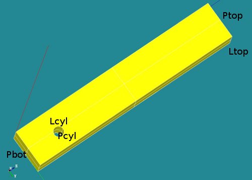
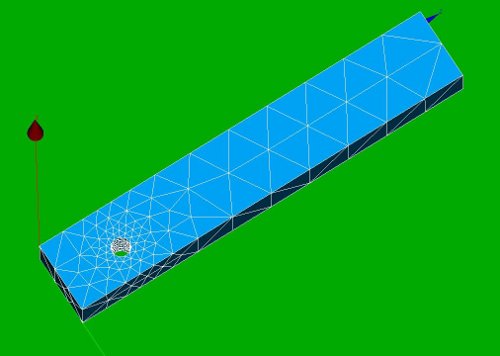
Geometry and mesh of the block with cylindrical hole
This contribution depends on the construction defined here. So please this contribution to find out the general behaviour of the construction: geometry, material properties and boundary conditions are given there.
This construction shows the use of LIAISON_DDL to simulate boundary condition on a cylindrical hole. It just shows the use of it: -the code is far from general. This may be improved in future versions.
Some images of the construction:
-
 *
* 


A number of groups has been defined (P for plane, L for line segments):
- Ptop (not used)
- Pbot (not used)
- Pcyl (could be used to define nodes on this surface)
- Lcyl (not used in final version) and
- Ltop, used to apply boundary conditions in x and y direction.
The boundary conditions in detail
- The first boundary condition on the line segment Ltop is easy to define:
- bcforce=AFFE_CHAR_MECA(MODELE=Cmod,DDL_IMPO=(_F(GROUP_MA='Ltop',DY=0.5,DX=0.0000),),);
- The cylindrical boundary condition on the nodes of the cylindrical hole are defined by the LIAISON_DDL keyword in stead of DDL_IMPO:
- ... LIAISON_DDL=(_F(NOEUD=('Ni','Ni','Ni'),DDL=('DX','DY','DZ'),COEF_MULT=(alpha1,alpha2,alpha3),COEF_IMPO=beta),
Using this keyword and selecting all the nodes for Ni can simulate a tangential boundary condition.
- ... LIAISON_DDL=(_F(NOEUD=('Ni','Ni','Ni'),DDL=('DX','DY','DZ'),COEF_MULT=(alpha1,alpha2,alpha3),COEF_IMPO=beta),
Now remember that the part in the _F(...) operator can be replaced by a Python script that has the following list, dictionary, or tuple, eg:
_F(NOEUD=('N1','N1','N1'),DDL=('DX','DY','DZ'),COEF_MULT=(0.00,0.00,0.45),COEF_IMPO=0.00)
:::::::
_F(NOEUD=('N808','N808','N808'),DDL=('DX','DY','DZ'),COEF_MULT=(0.0, -0.36, -0.26),COEF_IMPO=0.00)
can be replaced by:
{'NOEUD': ['N1',  'N1',  'N1'  ],'COEF_MULT':[0.00,0.00, 0.45], 'COEF_IMPO':0.0,'DDL':['DX', 'DY', 'DZ']}
:::::
{'NOEUD': ['N808','N808','N808'],'COEF_MULT':[0.0,-0.36,-0.26], 'COEF_IMPO':0.0,'DDL':['DX','DY','DZ']}
Alright, this took me several days to find out just this. But once you know, it is easy.
Now just an image to recall why we need to restrict these degrees of freedom:

Remarks
- here I included the dof 'DX' with a coefficient alpha1 = 0.0 to make the script more general. The coefficient alpha1 is zero here because the axis of rotation is along the x-axis.
Adaption of the code - A - helpfull
Since we are going to use plane Python script language, we need to define:
DEBUT(PAR_LOT='NON')
We will also use the some modules defined in the ...Utilitai.partition folder:
#from partition import *  #you need to have the aster/STAx.x/bibpyt/Utilitai in the search folder
from Utilitai.partition import *
import numpy                    # can be very useful
CmeshCA = MAIL_PY()                    # Creating empty new MAIL_PY "class  istantiation"
CmeshCA.FromAster(Cmesh)               # Reading mesh Data From Aster using object referencing to the class function FromAster
NodeGroup  = CmeshCA.gno               # extracting nodes group (see help(MAiL_PY) for object methods reference)
NodesNcyl  = list(NodeGroup['Ncyl'])   # extracting all ids' of the Fz nodes group
bc_list    = []                        # initialise boundary conditions with empty python list
# Get Number of Nodes and Number of Element
nonu=CmeshCA.dime_maillage[0]   ## number of nodes
test=CmeshCA.dime_maillage[1]   ## number of elements
elnu=CmeshCA.dime_maillage[2]   ## number of elements
test=CmeshCA.dime_maillage[3]   ## number of elements
test=CmeshCA.dime_maillage[4]   ## number of elements
test=CmeshCA.dime_maillage[5]   ## min,max dimension: [0:5]
NodeList = list(CmeshCA.correspondance_noeuds)
ElemList = list(CmeshCA.correspondance_mailles)
ElemType = list(CmeshCA.tm)
Adaption of the code - B usefull
This part of the script extract the nodes and coordinates of the cylinder area that need to have the rotational degrees of freedom. Note that this group of nodes has already been defined in Salome. The group is called 'Ncyl'
#Get Node coordinates referenced from node sequence position
ncoor = CmeshCA.cn
print 'extracted coordinates'
print ncoor[0]
print ncoor[1]
print ':::::::::::'
print ncoor[nonu-2]
print ncoor[nonu-1]    # or use -1 only
# axis of cylinder (or rotation axis for testing)
y1 = 2.0
z1 = 3.0
countntop = 0
for ic in NodesNcyl:
  nx = ncoor[ic][0]
  ny = ncoor[ic][1]
  nz = ncoor[ic][2]
  icp1 = ic+1         # node numbers are increased by 1: Salome <--> Code Aster
  bc_list.append({'NOEUD': ['N%d'%(icp1),'N%d'%(icp1),'N%d'%(icp1)], 'DDL':['DX','DY','DZ'], 'COEF_MULT': [0.0,ny-y1,nz-z1],'COEF_IMPO':0.00})
  countntop+=1
# check format of bc_list
print ic,countntop,': ',bc_list[0]
print '::::::::::::::::::::::::::'
print ic,countntop,': ',bc_list[-1]
bc_list=AFFE_CHAR_MECA(MODELE=Cmod,LIAISON_DDL = bc_list,);
Now the list can be used in the AFFE_CHAR_MECA command just as the _F(...) operator:
result=MECA_STATIQUE(MODELE=Cmod,
                  CHAM_MATER=Amat,
                  EXCIT=(_F(CHARGE=bcforce,),
                         _F(CHARGE=cyl_list),),);
compared for instance with this (small part of the extraction):
cylco2=AFFE_CHAR_MECA(MODELE=Cmod,
     LIAISON_DDL =
       _F(NOEUD=('N162 ','N162 '),DDL=('DY','DZ'),COEF_MULT=( 0.312402110475 , -10.3238902922 ),COEF_IMPO=0.00),
       _F(NOEUD=('N12  ','N12  '),DDL=('DY','DZ'),COEF_MULT=( 0.0            , -9.55          ),COEF_IMPO=0.00),
       _F(NOEUD=('N695 ','N695 '),DDL=('DY','DZ'),COEF_MULT=(-0.443605677987 , -9.92440897899 ),COEF_IMPO=0.00),
       ...
       _F(NOEUD=('N765 ','N765 '),DDL=('DY','DZ'),COEF_MULT=(-0.162737538758 , -10.4195431962 ),COEF_IMPO=0.00),
       _F(NOEUD=('N551 ','N551 '),DDL=('DY','DZ'),COEF_MULT=( 0.107926195474 , -9.56313396066 ),COEF_IMPO=0.00),),);
Adding the boundary conditions to the calculation
Finally, the list is applied to the MECA_STATIQUE command.
result=MECA_STATIQUE(MODELE=Cmod,
                  CHAM_MATER=Amat,
                  EXCIT=(_F(CHARGE=bcforce,),
                         _F(CHARGE=bc_list),),);
The result should be the same, apart from machine precision of course.
The results of the calculation
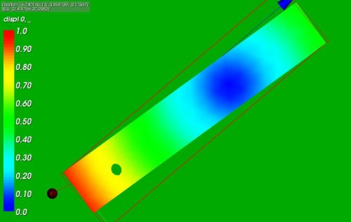
The following picture show the rotation of the block around the cylindrical hole:

- The left part of the picture displays the von Mises stresses in the construction: they are zero to the working precision as we expect. The rotation around the cylinder is controlled by the displacement at the top edge and can be performed by a rigid body movement.
- The right part shows the displacement in y direction: the construction nicely rotates around the cylindrical hole.
A bit of fooling around ...
Selecting the same nodes around the cylindrical hole but choosing the rotating point with an offset of 10 in z direction yields the following displacement:
* 

The code to generate this during the Salome session:
...
zoffset = 10.0  ## change to 10.0 for second picture
...
for allnode in Mbcyl.GetNodesId():
   countall+=1
   q1, q2, q3 = Mbcyl.GetNodeXYZ(allnode)
   # on cylinder yes/no:
   dy2 = (q2-y1)**2
   dz2 = (q3-z1)**2
   if abs(dy2+dz2-Rcyl2)<eps:
      countcyl+=1
      cnode = to_string(allnode)
      node_oncyl.append(allnode)
      #ss = []
      ss = "\n          _F(NOEUD=('N"+cnode+"','N"+cnode+"'),DDL=('DY','DZ'),COEF_MULT=("
      print ss,
      print (q2-y1),
      print ",",
      print (q3-z1-zoffset),
      print "),COEF_IMPO=0.00),",
   pass
pass
Input files for the FE Analysis and references
Input files:
- Python script for defining the geometry and mesh (blockrot4.py), load by File --> load script (cntrl T in the object browser), refresh (F5) after running
- Save the mesh file by right clicking in the object browser by right clicking on the mesh name Mbcyl; select Export to MED and accept or change the default values
- ASTK file (cylrot.astk, you need to edit the path to your requirements ...)
- command file (blockb.comm)
Download the files here:
- blockrot4.py and blockrot6.py basicly perform the same operation: selecting nodes on the cylinder. Though the way it is implemented is quite different: blockrot4 depends on the measures of the geometry whereas blockrot6 directly selects the nodes on the cylinder area by filters. See also [Salome] for more reference (and thank you JMB for the question asked there).
- blockrot7.py writes the liaison_ddl information to a file. Remember to change the path at line 109 to a suitable value for your system.
Reference:
[AFFE_CHAR_MECA, page 20/109]