Difference between revisions of "Contrib:KeesWouters/staticshell"
Keeswouters (Talk | contribs) (→''Solid element mesh'') |
Keeswouters (Talk | contribs) (→'''Hexahedron elements''') |
||
| Line 78: | Line 78: | ||
==='''Hexahedron elements'''=== | ==='''Hexahedron elements'''=== | ||
The following python file defines the geometry and the mesh of the plate. The mesh consists of hexahedron elements. The number of nodes and elements is largely controlled by the parameter Mfineness at the start of the file. Currently set to 0.15 it yields exactly 30k nodes. The number of layer along the thickness of the plate is 4. Setting different values for Mfineness (in the range from 0.0 to 0.6) yields between 2 and 12 layers. But for large values on my hardware only linear elements can be solved due to lack of memory. | The following python file defines the geometry and the mesh of the plate. The mesh consists of hexahedron elements. The number of nodes and elements is largely controlled by the parameter Mfineness at the start of the file. Currently set to 0.15 it yields exactly 30k nodes. The number of layer along the thickness of the plate is 4. Setting different values for Mfineness (in the range from 0.0 to 0.6) yields between 2 and 12 layers. But for large values on my hardware only linear elements can be solved due to lack of memory. | ||
| + | |||
| + | [[file:]] | ||
| + | |||
--[[User:Keeswouters|kwarky]] 14:44, 7 May 2009 (CEST) | --[[User:Keeswouters|kwarky]] 14:44, 7 May 2009 (CEST) | ||
Revision as of 13:42, 8 May 2009
Contents
Static behaviour of rectangular plate
The dynamics of a rectangular plate can be predicted quite well with shell (coque_3d) elements. I also liked to know the accuracy of the displacements for this kind of structures. A comparison between solid elements and shell elements has been made.
Dimensions of the plate The length and width of the plate are 1*1 m. The thickness of the shell elements has been increased to 0.02 m to enable meshing with solid elements (tetrahedrons and hexahedrons).
Boundary conditions and load Two types of boundary conditions have been given:
- clamped at one side (all displacements and rotations are suppressed)
- clamped at the four sides (all displacements and rotations are suppressed)
The load of the structure is a pressure of 0.1 bar on the surface of the plate
Material properties The The Young's module and poisson ratio for steel are set to 210 GPa and 0.28.
Displacement at the tip using beam theory
According to the shell theory the displacement of a beam the tip under uniform pressure is:
- w = q*L^4/(8*D)
- uniform pressure q = 10 kPa
- length of plate L = 1 m
- Youngs' module E = 210 GPa
- poisson ratio nu = 0.28
- bending stiffness D = Eh^3/(12*(1-nu*nu)) = 151910 Nm and
- displacement at the tip w = 8.2286 mm
Salome model of the rectangular plate
Shell elements
The geometry and meshing follows the same procedure as for the dynamics: geometry of the plate and generating the mesh.
Boundary conditions
For these calculations all the degree of freedoms (dofs) of one edge of the plate have been suppressed: three displacements and three rotations. This has been done in the corresponding comm file with the fillowing rule:
clamped=AFFE_CHAR_MECA(MODELE=modelc,
                       DDL_IMPO=(_F(GROUP_MA=('Linex0',),
                                   DX=0.0,
                                   DY=0.0,
                                   DZ=0.0,
                                   DRX=0.0,
                                   DRY=0.0,
                                   DRZ=0.0,),),
                        FORCE_COQUE=_F(GROUP_MA='shell',
                                   PRES=10.0e3,),);
Also the applied load has been given here in the last two lines. The group Linex0, of course, defines one edge of the plate.
For this load case the calculated displacement at the tip of the plate is
w_ca = 8.460 mm for a mesh with 40 nodes (3*3 quad8 elements) and
w_ca = 8.473 mm for a mesh with 2300 nodes.
In both cases this is slightly more than the theoretical value based on the shell theory: +2.8 % and +3.0 % for 40 and 2300 nodes respectively.
Media:Kw_shell2p3_deformed.jpg
Comparison to solid elements
So it may be noted that the shell elements converge fairly rapidly to the correct value (here they even overestimate the displacement, can that be explained?). We expect that for solid elements convergence will be much slower.
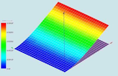
In the graph below the results of some calculations are shown. We have used tetrahedron and hexahedron elements, both linear and quadratic.

On the x-axis the number of nodes (thousands of nodes) are given. They range from 40 for the shell mesh to nearly 150k for the solid elements. On the vertical axis the calculated displacement is given where the convergence value is about 0.0082 m.
Note that the 150k nodes is about the maximum my hardware is able to handle. It needs about 3.5 GB ram for this calculation and my physical limit is 4 GB now.
So it is fair to say that linear elements will be much too stiff for normal cases. Therefor the displacements of the structure will be predicted much too low. There has been a discussion about this many times on the CAElinux forums, but I didnot expect that linear elements give such a large stiffness compared to quadratic elements.
(I will add some more Salome and comm files later on. Going for a break now)
Mesh with solid elements
For comparison solid elements have been used to determine the behaviour of the plate. It is very easy in Salome to change from linear to quadratic elements so I in most cases the calculation has been carried out with linear and quadratic elements using the same mesh grid. Saving the mesh into a med file before and after conversion to quadratic elements is all that needs to be done. Starting the Code Aster calculations by ASTK is just hitting the run button if all file and directories are set.
Hexahedron elements
The following python file defines the geometry and the mesh of the plate. The mesh consists of hexahedron elements. The number of nodes and elements is largely controlled by the parameter Mfineness at the start of the file. Currently set to 0.15 it yields exactly 30k nodes. The number of layer along the thickness of the plate is 4. Setting different values for Mfineness (in the range from 0.0 to 0.6) yields between 2 and 12 layers. But for large values on my hardware only linear elements can be solved due to lack of memory.
[[file:]]
--kwarky 14:44, 7 May 2009 (CEST)