Contrib:KeesWouters/shellsolid/liaisonmail
Contents
Connecting shells and solid elements by liaison_mail
[under construction .... not finished yet ... ]
To start with, this contribution mainly focuses on the use of Salome and Code Aster, not on the results and the mechanical justifications of the code that has been used. So no guarantee that the results will be correct up to the fifth decimal place, which they are not. I do hope though that this information is useful. For me it has been, because I had to think about some commands and look through the documentation and learn from that. In case of mistakes, errors or remarks, please notify me, or better, you are invited to correct or edit them yourself. Enjoy.
I stole a lot of ideas from the CaeLinux and Code Aster forums. So thank you for all who posted on this topic. This contribution is heavily based on the examples ssls101m and ssls101m in the atest directory
[As usual, the files that define the geometry, mesh and command files can be found at the end of this contribution.]
The construction
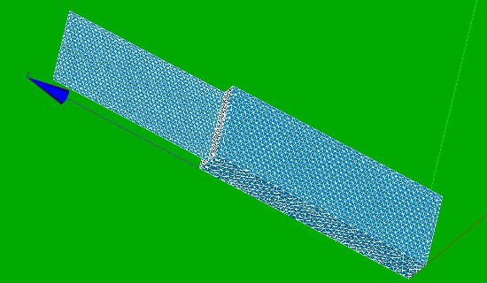
The geometry of the construction
- a number of method to establish a connection between shells to solid elements can be used:
- the Arlequin method
- use a region of solid nodes; this causes a rigid body between the interface of the shells and solids
- liason_mail, since version CAster 10.1.xx
As usual the geometry is quite simple in order not to disturb the issue we would like to show with other difficulties. The first part consists of a beam of height 23 [mm] and a cross section of 3*8 [mm2]. This part is modeled by solid elements. On top of this another beam of height 17 [mm] is added. The width of this beam is 8 [mm]. This part is modeled by shell elements, ie. only the 2D dimensions -height and width- are modeled here. The thickness of 1 [mm] is defined in the Aster command file.
The geometry is defined in a python script (for download see end of this contribution) and can be loaded into Salome Geometry module by File --> Load script (or ctrl T in the object browser window). Right click Refresh or push F5 after loading if necessary.

- x direction is out-of-plane of the shell
- z direction is in the main direction of the construction
- width of block and shell: 8 mm
- thickness of block 3 mm; thickness of shell 1 mm, defined in Code Aster
- height of block 23 mm; height of shell 17 mm
- groups defined in Salome
- volume block
- shell area shell, FBbot and FBtop
- connection line between shells and solids Cline
The mesh of the construction
For we command file in Code Aster we need various parts (or groups in Salome) to apply boundary conditions, forces, material properties and such. These groups are depicted in the image above:
- the bottom and top surface of the block FBbot and FBtop,
- the solid element region block,
- the shell elements shell and
- the two vertices on top edge of the shell elements: Nforce
-
 :
: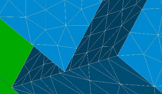


Again, the mesh of the construction is defined in a python script.
First, a mesh with linear elements has been used (tetra4 and tria3 elements) that can be used with DKT modelisation. Later a quadratic mesh with tetra10 and tria6 elements have been employed. This will provide us with a better converging solution, but makes the command file a bit more complex because we need to modify the tria6 to a tria7 mesh for coque_3d finite elements. The coque_3d element has an extra node at the centre of it.
Relevant part of the command file
The boundary conditions are applied on FBbot: all displacements of this surface are restricted. The forces are applied on the two nodes Nforce in the out-of-plane or x direction and the magnitude is 10 N each, ie. 20 N in total. The material properties of both the shell and solid elements are steel.
#SVmesh=LIRE_MAILLAGE(...);
#SVmodel=AFFE_MODELE(INFO=1,
                   MAILLAGE=SVmesh,
                  AFFE=(_F(GROUP_MA='block',PHENOMENE='MECANIQUE',MODELISATION='3D',),
                       _F(GROUP_MA='shell',PHENOMENE='MECANIQUE',MODELISATION='DKT',),),);
#Steel=DEFI_MATERIAU(ELAS=_F(E=210000,NU=0.3,),);
#Assigns a physical model
#thickness = 1.000
#Shell=AFFE_CARA_ELEM(INFO=1,
                    MODELE=SVmodel,
                    COQUE=_F(GROUP_MA='shell',
                             EPAIS=thickness,
                             VECTEUR=(0.0,1.0,0.0),# defines local x-axis of shell, default global x-axis
                             EXCENTREMENT=0.000,
                             COQUE_NCOU=1,  # 1 for non linear STAT_NON_LINE et DYNA_NON_LINE
                             INER_ROTA='OUI',),); # inertia of rotation: DKT, DST et Q4G

#chnorm = CREA_CHAMP(TYPE_CHAM='NOEU_GEOM_R',
                   OPERATION='NORMALE',
                   MODELE= SVmodel,
                   GROUP_MA='shell',
                   INFO=1);
#ConShSol=AFFE_CHAR_MECA(MODELE=SVmodel,
                       LIAISON_MAIL =_F(TYPE_RACCORD='COQUE_MASSIF',
                                        #GROUP_NO_ESCL='Cline',
                                        GROUP_MA_ESCL='Cline',
                                        GROUP_MA_MAIT='block',
                                        CHAM_NORMALE=chnorm,
                                        EPAIS=thickness,))
#Mat=AFFE_MATERIAU(...);
#force=AFFE_CHAR_MECA(MODELE=SVmodel,
                   DDL_IMPO=_F(GROUP_MA='FBbot',
                               LIAISON='ENCASTRE',),
                   FORCE_NODALE=_F(GROUP_NO='Nforce',
                                   FX=10.00,),);
#SVresult=MECA_STATIQUE(MODELE=SVmodel,
                      CHAM_MATER=Mat,
                      CARA_ELEM=Shell,
                      EXCIT=(_F(CHARGE=force,),
                             _F(CHARGE=ConShSol,),),);
Liaison_mail keyword in AFFE_CHAR_MECA
The additional part that replace the Arlequin method in the previous part is:
#ConShSol=AFFE_CHAR_MECA(MODELE=SVmodel,
                       LIAISON_MAIL =_F(TYPE_RACCORD='COQUE_MASSIF',
                                        #GROUP_NO_ESCL='Cline',
                                        GROUP_MA_ESCL='Cline',
                                        GROUP_MA_MAIT='block',
                                        CHAM_NORMALE=chnorm,
                                        EPAIS=thickness,))
The LIAISON_MAIL keyword takes the TYPE_RACCORD as a parameter. Valid parameters are
- COQUE_MASSIF for a connection between solids and shells
- COQUE for a connection between two incompatible shells (eg DKT and COQUE_3D modelisation)
- .....
In this case we have a solid part and shell, so we use TYPE_RACCORD='COQUE_MASSIF'. The three keywords GROUP_MA_ESCL, GROUP_MA_MAIT and CHAM_NORMALE define the geometry between the interconnection. In this case the block is the master group defined by GROUP_MA_MAIT. The slave is the connection line between the solid and the shells defined by GROUP_MA_ESCL='Cline'. The shell part is defined by CHAM_NORMALE=chnorm but a transition need to be carrried out first by
#chnorm = CREA_CHAMP(TYPE_CHAM='NOEU_GEOM_R',
                   OPERATION='NORMALE',
                   MODELE= SVmodel,
                   GROUP_MA='shell',
                   INFO=1);
since LIAISON_MAIL does not accept a string as an input parameter (as far as I understand the error message correctly).
Note that GROUP_MA_ESCL, GROUP_MA_MAIT and CHAM_NORMALE(GROUP_MA...) can be replaced by there node equivalents: GROUP_NO_ESCL, GROUP_NO_MAIT and CHAM_NORMALE(GROUP_NO...)
Results
Since C_Aster version10.1.19??? (ckeck) it is possible to connect solid-shell, shell-shell directly by LIAISON_MAIL. No interconnecting regions are needed then as in Arlequin. For more details look [here ....(tbd)]. Here are some first results:
- For Liaison_mail with linear elements (DKT)
#displacements at nodes on group Nforce
#displacements of top vertices
* INTITULE         * NOEUD    * RESU     * NOM_CHAM         * NUME_ORDRE   * INST         * ABSC_CURV    * COOR_X       * COOR_Y       * COOR_Z       * DX           * DY           * DZ
* displacements    * N3494    * SVresult * DEPL             *            1 *  0.00000E+00 *  0.00000E+00 *  1.50000E+00 *  8.00000E+00 *  4.00000E+01 *  3.27736E-01 *  1.19326E-05 *  1.60472E-06
* displacements    * N5015    * SVresult * DEPL             *            1 *  0.00000E+00 *  8.00000E+00 *  1.50000E+00 *  0.00000E+00 *  4.00000E+01 *  3.27709E-01 *  1.19330E-05 *  5.41754E-06

Links
This contribution is based on the astest files ssls101m and ssls101n that are described here: ssls101