Contrib:KeesWouters/plasticity
Contents
- 1 V shaped construction under plastic deformation
- 2 General procedure of the calculation
- 3 Non linear material properties
- 4 Boundary conditions and loads
- 5 Perform the calculation
- 6 Results for post processing by Salome
- 7 Write displacements and nodal forces to table and file
- 8 Download input and output files
V shaped construction under plastic deformation
The V shaped is defined by an extrusion of a V shaped face.
-
 *
* 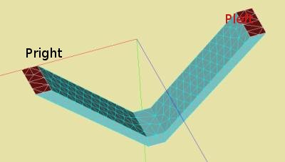


Three planes are defined in the geometry: Pleft and Pright for applyind boundary conditions (dx=dy=dz=0) and Pforce for defining a prescribed displacement in y direction.
The definition of the geometry as well as the meshing is given in the Python input file.
In the geometry module of Salome select File --> Load Script (or ctrl T) and thereafter the file: Media:kw_gm_vshape.zip.
General procedure of the calculation
The general procedure of the calculation is as follows:
- read the mesh, define models, meshes
- apply the non linear material properties of the construction
- define the boundary conditions
- define the maximum load, in this case a maximum displacement at the plane Pforce
- define 'time' and 'load' increments
- perform the analysis
- define results in a med-file for Salome, in this case, displacements, vonMises and plastic stresses
- print results in a file, notably the displacements of the plane Pforce and its corresponding forces.

In the figure the results of four load cycles are given: the maximum displacement of each calculation is 0.080, 0.085, 0.095 and 0.100 mm. The plastic deformation at a load free construction after the load cycle is roughly 0.005, 0.009, 0.018 and 0.022 mm.
Each dot in the curves indicate a output point of the calculation. In most case 21 points are given, these have been defined in the 'time' increment function.
Non linear material properties
The linear material behaviour of steel is defined by the Young's modulus E = 210 GPa.

The plastic material behaviour is defined by TRACTTION and a table of (eps_i - sigma_i), as indicated in the figure. In the keyword DEFI_MATERIAU apart from Young's modulus and poisson ratio, now TRACTION is given for the non linear (eps-sigma) relation. The command AFFE_MATERIAU assigns the material to the complete mesh.
#Material properties
Traction=DEFI_FONCTION(NOM_PARA='EPSI',
                       VALE=(1.6e-3,300.0,
                             2.0e-2,400.0,
                             1.0e-1,450.0,
                             1.5e-1,473.0,
                             2.0e-1,500.0,
                             3.0e-1,550.0,),
                       INTERPOL='LIN',
                       PROL_DROITE='LINEAIRE',
                       PROL_GAUCHE='EXCLU',);
#define plastic behaviour of steel by Traction
steel=DEFI_MATERIAU(ELAS=_F(E=2.1e5,NU=0.27,),
                    TRACTION=_F(SIGM=Traction,),);
#assign material steel to the whole construction
matprops=AFFE_MATERIAU(MAILLAGE=pmesh,AFFE=_F(TOUT='OUI',MATER=steel,),);
Boundary conditions and loads
In Code Aster boundary conditions and loads are treated in the shame way. So no distinction need to be made between them. In the mesh we defined three groups for applying boundary conditions and loads: for fixed boundary conditions Pleft and Pright. In the command file they are united to one group Pfix by the command:
pmesh=DEFI_GROUP(reuse =pmesh,
                   MAILLAGE=pmesh,
                   CREA_GROUP_MA=(_F(NOM='Pfix',UNION= ('Pleft','Pright',),),),);
Of course, this could have been done in Salome just as well.
The boundary condition itself are given by:
LoadFix=AFFE_CHAR_MECA(MODELE=pmode,
                   FACE_IMPO=(_F(GROUP_MA='Pfix',
                                 DX=0.0,DY=0.0,DZ=0.0,),),);
The load will be applied in steps defined by a 'time' function and multiplification factor on the load.
ydisp = 0.1000
LoadPres=AFFE_CHAR_MECA(MODELE=pmode,
                   FACE_IMPO=(_F(GROUP_MA='Pforce',DY=ydisp,),),);
tsteps = 21
time=DEFI_LIST_REEL(DEBUT=0.0,
                   INTERVALLE=_F(JUSQU_A=2.1,NOMBRE=tsteps,),
                   INFO=2,TITRE='time',);
ramp=DEFI_FONCTION(NOM_PARA='INST',
                  VALE=(0.00,0.00,
                        1.00,1.00,
                        1.10,1.00,
                        2.10,0.00,),
                  INFO=2,TITRE='ramp',);
- the time is defined from 0.0 to 2.1 and stepsize 0.1 s, yielding 21 points.
- The load multiplication factor is defined by ramping from 0.0 to 1.0 during the first 1 s,
- then keep it constant at 1.0 for 0.1 s and
- decreasing from 1.0 to 0.0 in the last second.

At some step, e.g. step 14, the 'time' is 1.4 s and the corresponding multiplication factor for the load is 0.7, i.e. for the y displacement DY = 0.7*0.1000 = 0.070 mm.
Perform the calculation
The command for the static non linear case is STAT_NON_LINE
Presul=STAT_NON_LINE(MODELE=pmode,
                     CHAM_MATER=matprops,
                     EXCIT=(_F(CHARGE=LoadFix,),
                            _F(CHARGE=LoadPres,FONC_MULT=ramp,),),
                     COMP_INCR=_F(RELATION='VMIS_ISOT_TRAC',
                                  DEFORMATION='SIMO_MIEHE',
                                  TOUT='OUI',),
                     INCREMENT=_F(LIST_INST=time,
                                  SUBD_PAS=10,
                                  SUBD_PAS_MINI=0.005,),
                     NEWTON=_F(REAC_INCR=1,
                               MATRICE='TANGENTE',
                               REAC_ITER=1,),
                     CONVERGENCE=_F(ITER_GLOB_MAXI=20,),
                     ARCHIVAGE=_F(PAS_ARCH=1,),);
The keywords MODELE and CHAM_MATER define the model and material properties assigned in previous commands (not discussed here, see Python input file below).
The loadcase is defined by the keyword EXCIT and takes as parameters the boundary conditions and prescribed displacements of the plane Pforce. The multiplication factor is defined by the function FONC_MULT=ramp, where ramp is the previously discussed function.
The COMP_INCR defines what type of deformation (SIMO_MIEHO) and constitutive model are to be used.
In INCREMENT the previously defined 'time' function indicates stepsize and, when the solution does not converge, possible divisions are given.
.....
Results for post processing by Salome
If the calculation converges the results can be extracted. Here the displacements, von Mises stresses and plastic strains are stored for visualisation by Salome.
- Compute (VonMises) Stress / Strain
Presul=CALC_ELEM(reuse =Presul,
                 RESULTAT=Presul,
                 OPTION=('SIEF_ELNO_ELGA','EPSI_ELNO_DEPL','EPSP_ELNO','EQUI_ELNO_SIGM','EQUI_ELNO_EPSI',),);
- Write Results to MED file
- displacements DEPL (x, y and z component)
- vonMisses stresses EQUI_ELNO_SIGM (vonmisses component only)
- plastic strains EPSP_ELNO (six components epsxx, epsyy, ...)
IMPR_RESU(FORMAT='MED',
         UNITE=21,
         RESU=(_F(MAILLAGE=pmesh,
                  RESULTAT=Presul,
                  NOM_CHAM='DEPL',
                  NOM_CMP=('DX','DY','DZ',),),
               _F(MAILLAGE=pmesh,
                  RESULTAT=Presul,
                  NOM_CHAM='EQUI_ELNO_SIGM',
                  NOM_CMP='VMIS',),
                _F(MAILLAGE=pmesh,
                  RESULTAT=Presul,
                  NOM_CHAM='EPSP_ELNO',
                  NOM_CMP=('EPXX','EPYY','EPZZ','EPXY','EPXZ','EPYZ',),),),);
Write displacements and nodal forces to table and file
Since we applied a displacement on the plane Pforce, which is easier to control the convergence, we are interested in the reaction forces on this plane.
First we determine the nodal forces and reaction on the nodes ('FORC_NODA','REAC_NODA')
- calculate nodal equivalents and reaction forces
Presul=CALC_NO(reuse =Presul,
            RESULTAT=Presul,
            OPTION= ('SIGM_NOEU_DEPL','EQUI_NOEU_SIGM','FORC_NODA','REAC_NODA',),);
Then define a group of nodes from the mesh plane Pforce
pmesh=DEFI_GROUP(reuse =pmesh,
                MAILLAGE=pmesh,
                CREA_GROUP_NO=_F(NOM='Nreac',GROUP_MA='Pforce',),);
Create a table for displacements ('DEPL'), reaction forces ('REAC_NODA') and nodal forces ('FORC_NODA'). In all three cases the three directions x, y and z (RESULTANTE=('DX','DY','DZ',)) will be extracted. Since no reaction forces?????? are present on this selected group of nodes, basically both fields are the same.
TB_nodf=POST_RELEVE_T(ACTION=(_F(OPERATION='EXTRACTION',
                               INTITULE='displacements',
                               RESULTAT=Presul,
                               NOM_CHAM='DEPL',
                               TOUT_ORDRE='OUI',
                               GROUP_NO='Nforce',
                               RESULTANTE=('DX','DY','DZ',),
                               MOYE_NOEUD='NON',),
                            _F(OPERATION='EXTRACTION',
                               INTITULE='ReactionForces',
                               RESULTAT=Presul,
                               NOM_CHAM='REAC_NODA',
                               TOUT_ORDRE='OUI',
                               GROUP_NO='Nreac',
                               RESULTANTE=('DX','DY','DZ',),
                               MOYE_NOEUD='NON',),
                            _F(OPERATION='EXTRACTION',
                               INTITULE='NodalForces',
                               RESULTAT=Presul,
                               NOM_CHAM='FORC_NODA',
                               PRECISION=0.000001,
                               GROUP_NO='Nreac',
                               RESULTANTE=('DX','DY','DZ',),),),
                            TITRE='[Reaction] Nodal Forces',);
Finally, write the data to a file (adjust a file in ASTK with, in this case file unit 26).
IMPR_TABLE(TABLE=TB_nodf,
        FORMAT='TABLEAU',
        UNITE=26,
        SEPARATEUR=' * ',
        TITRE='displacements at nodes on group Nforce',);
The picture with the force - displacements at the start has been created with these numbers.
For more information regarding available fields, quantities and components see: http://www.code-aster.org/DOCASTER/Man_U/U5/U50101c.pdf and http://www.code-aster.org/DOCASTER/Man_U/U2/U20104b2.pdf
Download input and output files
So far. Any comments welcome. augustus 2009