Difference between revisions of "Contrib:KeesWouters/bc/cylinder"
From CAELinuxWiki
Keeswouters (Talk | contribs) m |
Keeswouters (Talk | contribs) |
||
| Line 2: | Line 2: | ||
#* key words | #* key words | ||
#** LIAISON_DDL | #** LIAISON_DDL | ||
| + | |||
| + | |||
| + | =='''Geometry and mesh of the block with cylindrical hole'''== | ||
| + | |||
| + | This is a very simple construction to show the use of ''LIAISON_DDL'' to simulate boundary condition on a cylindrical hole. It just shows the use of it: -the code is far from general. This may be improved in further versions. | ||
| + | |||
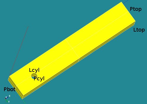
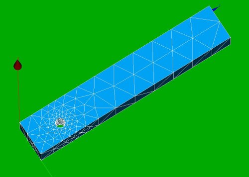
| + | The geometry consists of a block with a cylindrical hole near the bottom side. The overall dimensions of the block are [Lx * Ly * Lz] = [2 * 3 * 20 ]. The hole is placed on the x-plane at position [yc, zc] = [2 3]. The radius of the hole is R=0.45. | ||
| + | |||
| + | : [[image:kw_bcylgeom.jpg]] * [[image:kw_spring_bcylmesh.jpg]] | ||
| + | |||
| + | A number of groups has been defined (P for plane, L for line segments): | ||
| + | * Ptop | ||
| + | * Pbot | ||
| + | * Pcyl | ||
| + | * Lcyl and | ||
| + | * Ltop | ||
| + | |||
| + | =='''Material properties of the block'''== | ||
| + | The material property of the block is set to steel. | ||
| + | |||
| + | =='''The boundary conditions'''== | ||
| + | * On the top line segment Ltop a non zero displacement in y direction is prescribed. The displacement is z direction is fixed. | ||
| + | * On the nodes connected to the cylindrical hole a tangential displacement is allowed. The radial component is fixed. The displacement in axial or x direction is free. Due to this restriction the displacement of the geometry in z direction is defined. | ||
| + | |||
| + | ===''The boundary conditions in detail''=== | ||
| + | * The first boundary condition on the line segment Ltop is easy to define: | ||
| + | ** bcforce=AFFE_CHAR_MECA(MODELE=Cmod,DDL_IMPO=(_F(GROUP_MA='Ltop',DY=0.5,DX=0.0000),),); | ||
| + | |||
| + | * The cylindrical boundary condition on the nodes of the cylindrical hole are defined by the LIAISON_DDL keyword: | ||
| + | ** ... LIAISON_DDL=(_F(NOEUD=('Ni','Ni'),DDL=('DY','DZ'),COEF_MULT=(alpha1,alpha2),COEF_IMPO=beta), | ||
Revision as of 15:58, 7 August 2010
- Applying cylinder boundary conditions
Applied on a simple block with a cylindrical hole the use of LIAISON_DLL is used to show the simulation of a cylindrical coordinate system
Contrib:KeesWouters/bc/cylinder- key words
- LIAISON_DDL
- key words
Contents
Geometry and mesh of the block with cylindrical hole
This is a very simple construction to show the use of LIAISON_DDL to simulate boundary condition on a cylindrical hole. It just shows the use of it: -the code is far from general. This may be improved in further versions.
The geometry consists of a block with a cylindrical hole near the bottom side. The overall dimensions of the block are [Lx * Ly * Lz] = [2 * 3 * 20 ]. The hole is placed on the x-plane at position [yc, zc] = [2 3]. The radius of the hole is R=0.45.
-
 *
* 


A number of groups has been defined (P for plane, L for line segments):
- Ptop
- Pbot
- Pcyl
- Lcyl and
- Ltop
Material properties of the block
The material property of the block is set to steel.
The boundary conditions
- On the top line segment Ltop a non zero displacement in y direction is prescribed. The displacement is z direction is fixed.
- On the nodes connected to the cylindrical hole a tangential displacement is allowed. The radial component is fixed. The displacement in axial or x direction is free. Due to this restriction the displacement of the geometry in z direction is defined.
The boundary conditions in detail
- The first boundary condition on the line segment Ltop is easy to define:
- bcforce=AFFE_CHAR_MECA(MODELE=Cmod,DDL_IMPO=(_F(GROUP_MA='Ltop',DY=0.5,DX=0.0000),),);
- The cylindrical boundary condition on the nodes of the cylindrical hole are defined by the LIAISON_DDL keyword:
- ... LIAISON_DDL=(_F(NOEUD=('Ni','Ni'),DDL=('DY','DZ'),COEF_MULT=(alpha1,alpha2),COEF_IMPO=beta),