Difference between revisions of "Contrib:BondMatt/TurbulentPipeFlow"
(→Geometry/Mesh) |
|||
| Line 43: | Line 43: | ||
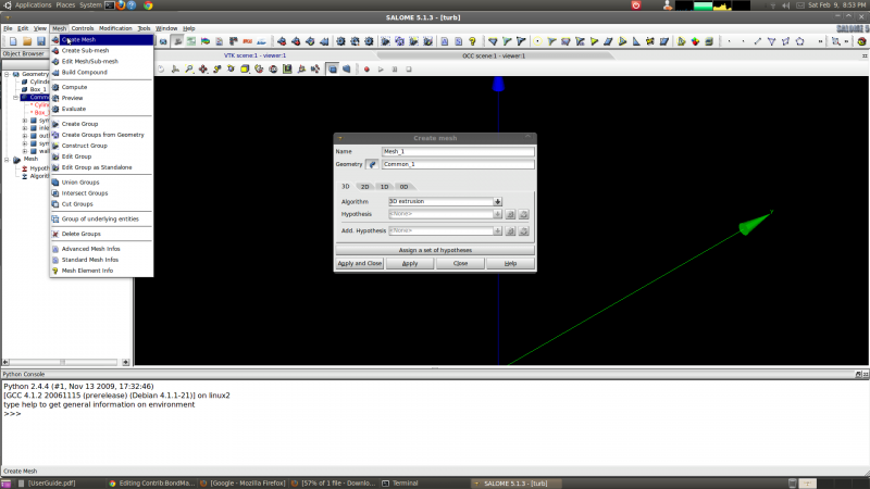
Switching to the meshing interface, the procedure for creating a mesh was to first create global meshing settings by going to the Mesh menu and selecting Create Mesh. In the dialog box that pops up the Geometry entity Common_1 is selected and the 3D meshing Algorithm '3D extrusion' is selected (shown in the figure below). | Switching to the meshing interface, the procedure for creating a mesh was to first create global meshing settings by going to the Mesh menu and selecting Create Mesh. In the dialog box that pops up the Geometry entity Common_1 is selected and the 3D meshing Algorithm '3D extrusion' is selected (shown in the figure below). | ||
| − | [[Image:Mesh_1.png]] | + | [[Image:Mesh_1.png|800x500px]] |
Revision as of 04:01, 10 February 2013
Introduction
This tutorial will attempt to follow as closely as possible the turbulent pipe flow Fluent tutorial available on Cornell's website but will use the open source CFD solvers Code Saturne and OpenFOAM.
The model is very similar to the laminar pipe flow tutorial with the exception of the dynamic viscosity which is two orders of magnitude smaller at 2E-5kg/m/s. Therefore the Reynolds number, or ratio of inertial to viscous forces, is two order of magnitude higher with a value of 10 000. The flow will clearly be turbulent since viscous forces are minimal and damping will be essentially non existent. Laminar flow can be experimentally observed at much larger Reynolds numbers (up to approximately 100 000 if my memory serves me correctly) with very smooth pipes (I believe ceramics were used in some research) and controlled conditions. This makes sense, with no external disturbance and very low pipe roughness perturbations will be minimal.
Software Versions:
Ubuntu 8.04 LTS
Salome V4.1.4
Code Saturne V1.4.a (GUI)
OpenFOAM 2.0
Fluent Tutorial
The Cornell University Fluent tutorial can be found here [1].
Is it just me or are the variables 'd' and 'D' reversed in the figure?
Geometry/Mesh
Geometry
The geometry is identical to the previous tutorial. I was hoping to convert the OpenFOAM/snappyHexMesh coarse hexahedron mesh for use with Code Saturne but there is no direct conversion tool in OpenFOAM or that I could find online. It might be possible to manually convert the mesh if the file is ASCII text and perhaps I will try to do this and add it. For now I will create a mesh in the MED format in Salome. I may try to convert it to a format compatible with OpenFOAM. I think I still have the old Code Saturne files for the laminar tutorial but they would be on a laptop with a dead GPU.
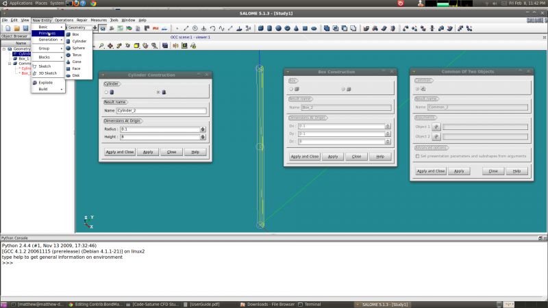
First step was to create a quarter of a cylinder with a radius of 0.1 meters and a length of 8 meters. This was done by first creating a cylinder with the 'Create a cylinder' tool which can be accessed through a toolbar (at least in my installation) or through the 'New Entity' menu and 'Primitives'. I also created a box with dimensions of 0.1 X 0.1 X 8 meters. This was followed by a Boolean operation to extract the common or overlapping region.
The next step was to 'Explode' the entity created by the Boolean operation through the 'New Entity' menu. The quarter cylinder was exploded into faces so that they could be re-named for boundary conditions. Mesh cells and/or nodes associated with these surfaces can be identified and grouped by Salome at the meshing stage for boundary conditions in the solver. Reasonable names like: wall, sym1, sym2, inlet, and outlet were used.
Mesh
Switching to the meshing interface, the procedure for creating a mesh was to first create global meshing settings by going to the Mesh menu and selecting Create Mesh. In the dialog box that pops up the Geometry entity Common_1 is selected and the 3D meshing Algorithm '3D extrusion' is selected (shown in the figure below).

