Difference between revisions of "Contrib:Claws/Code Aster/10 x cases/liaison mail"
m (Contrib:Claws/Code Aster/10 1 x cases/liaison mail moved to Contrib:Claws/Code Aster/10 x cases/liaison mail) |
|||
| Line 7: | Line 7: | ||
== Introduction and theory == | == Introduction and theory == | ||
| − | In this case we'll use '''Salomé''', '''ASTK''' and '''Code_Aster''' to load and combine several separate mesh files into one big mesh and solve for an applied load. | + | In this case we'll use '''Salomé''', '''ASTK''' and '''Code_Aster''' to load and combine several separate mesh files into one big mesh and solve for an applied load. Then separate the mesh again, now containing the calculated fields. |
| − | The reasons for this approach can be many, | + | |
| + | |||
| + | The reasons for this approach can be many, such as Salomé running out of available memory, operations take exceedingly long to complete because the whole mesh has to be displayed/updated etc., or sometimes it's just more practical to work on one part of an assembly instead of the full assembly. | ||
In Salomés geometry module the full assembly is manipulated in different ways, but each of the parts are meshed and exported separately. | In Salomés geometry module the full assembly is manipulated in different ways, but each of the parts are meshed and exported separately. | ||
| Line 24: | Line 26: | ||
*Assign unit numbers in '''ASTK''' | *Assign unit numbers in '''ASTK''' | ||
| − | *Tell '''Code_Aster''' which mesh files to read using unit numbers and tell it which surfaces | + | *Tell '''Code_Aster''' which mesh files to read using unit numbers and tell it which surfaces should be glued together. |
| + | |||
| + | *Calculate the results, then print results to each separate mesh | ||
| Line 41: | Line 45: | ||
| [[Image:Claws_assm_geo5.jpg|thumb|center|"Part:Assembly exploded"]] | | [[Image:Claws_assm_geo5.jpg|thumb|center|"Part:Assembly exploded"]] | ||
| [[Image:Claws_assm_geo4.jpg|thumb|center|"Part:Assembly"]] | | [[Image:Claws_assm_geo4.jpg|thumb|center|"Part:Assembly"]] | ||
| − | |||
|} | |} | ||
| Line 51: | Line 54: | ||
You should be familiar with assigning groups, meshing and exporting files in Salomé, so I will not go through it here. Consult the '''.hdf''' file I've attached at the bottom of the page. | You should be familiar with assigning groups, meshing and exporting files in Salomé, so I will not go through it here. Consult the '''.hdf''' file I've attached at the bottom of the page. | ||
| + | '''note''': I have used Salomé 5.1.5 to generate the mesh, so the '''.hdf''' might not be backwards compatible. To recreate the mesh, use the included '''.brep''' files, the diagram below, and use 'automatic tetrahedralization' with a average/local size of 3. | ||
<br\> | <br\> | ||
Revision as of 22:59, 2 March 2011
<-Link: Back to Contrib:Claws/Code_Aster/10_1_x_cases
Contents
Content
UNDER CONSTRUCTION
Introduction and theory
In this case we'll use Salomé, ASTK and Code_Aster to load and combine several separate mesh files into one big mesh and solve for an applied load. Then separate the mesh again, now containing the calculated fields.
The reasons for this approach can be many, such as Salomé running out of available memory, operations take exceedingly long to complete because the whole mesh has to be displayed/updated etc., or sometimes it's just more practical to work on one part of an assembly instead of the full assembly.
In Salomés geometry module the full assembly is manipulated in different ways, but each of the parts are meshed and exported separately.
A section of the assembly below, is what we'll be working with.

Work flow
To accomplish this feat using Salomé, ASTK and Code_Aster, a few steps must be completed.
- Decide which surfaces of the parts that will be 'glued' together and assign mesh groups accordingly
- Assign unit numbers in ASTK
- Tell Code_Aster which mesh files to read using unit numbers and tell it which surfaces should be glued together.
- Calculate the results, then print results to each separate mesh
Below in the table the different parts that go into the assembly can be seen.
| Tables | Are | Fun |
|---|---|---|


<br\>
Assignment of groups in Salomé
You should be familiar with assigning groups, meshing and exporting files in Salomé, so I will not go through it here. Consult the .hdf file I've attached at the bottom of the page.
note: I have used Salomé 5.1.5 to generate the mesh, so the .hdf might not be backwards compatible. To recreate the mesh, use the included .brep files, the diagram below, and use 'automatic tetrahedralization' with a average/local size of 3. <br\>

<br\>
ASTK setup
Each exported mesh file is assigned a unique unit number in ASTK so Code_Aster can recognize them during parsing of the .comm file.
<br\>
 <br\>
<br\>
- Assigning the mesh files in ASTK
- mmed for mesh file
- local file
- Name of file on disk
- LU: unique number correspondent to a number in the .comm file
- D for Data
- LU: unique number correspondent to a number in the .comm file
- Name of file on disk
- local file
- mmed for mesh file
<br\>
Code_Aster setup
The way Code_Aster connects different meshes, is by using the LIAISON_MAIL command (see U4.44.01 section 4.14).
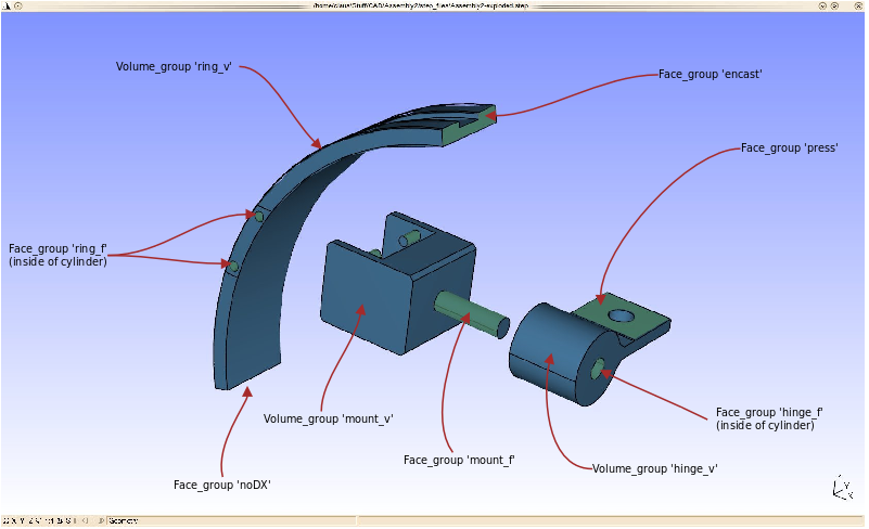
A 3D volume group is connected to a 2D face group using a 'parent/child' relationship called GROUP_MA_MAIT and GROUP_MA_ESCL - this explains why the parts in the group diagram (in the Salomé paragraph) are assigned groups called name_f for face and name_v for volume.
Heres a diagram of the boundary conditions - They will be explained further in the .comm file.

.comm file, step by step
#Claws - Jan - 2010
#For www.CAELinux.com

DEBUT();

MA=DEFI_MATERIAU(ELAS=_F(E=2.1e5,
                        NU=0.28,),);
- Definition
- Self serving credits and date
- DEFI_MATERIAU: Define material, assign the name MA to it.
- ELAS: We only deal with a regular elastic material here, with an elasticity module (Young's module) of 210 GPA and a Poisson's ratio of 0.28
ring=LIRE_MAILLAGE(UNITE=20,
                  FORMAT='MED',);

mount=LIRE_MAILLAGE(UNITE=21,
                   FORMAT='MED',);

hinge=LIRE_MAILLAGE(UNITE=22,
                   FORMAT='MED',);
- Definition
- Read each of the mesh files assigned in ASTK
- UNITE: Uniquely assigned number in ASTK (LU)
- Read each of the mesh files assigned in ASTK
mesh1=ASSE_MAILLAGE(MAILLAGE_1=hinge,
                   MAILLAGE_2=mount,
                   OPERATION='SUPERPOSE',);

mesh2=ASSE_MAILLAGE(MAILLAGE_1=mesh1,
                   MAILLAGE_2=ring,
                   OPERATION='SUPERPOSE',);
- Definition
- ASSE_MAILLAGE - Assemble mesh (See U4.23.03 for explanation)
- mesh1: 'Assemble' two mesh files hinge and mount - use superposition or 'overlay'
- mesh2: 'Assemble' two mesh files - This time use the mesh1 previously created and add ring to the combined mesh - use superposistion or 'overlay'
- ASSE_MAILLAGE - Assemble mesh (See U4.23.03 for explanation)
linmod=AFFE_MODELE(MAILLAGE=mesh2,
                  AFFE=_F(TOUT='OUI',
                          PHENOMENE='MECANIQUE',
                          MODELISATION='3D',),);

mesh2=MODI_MAILLAGE(reuse =mesh2,
                   MAILLAGE=mesh2,
                   ORIE_PEAU_3D=_F(GROUP_MA='press',),);
- Definition
- Assign a 3D mechanical model to everything on mesh2
- Reorient the normals of the 'press' face group
Qmesh=CREA_MAILLAGE(MAILLAGE=mesh2,
                   LINE_QUAD=_F(TOUT='OUI',),);

qmod=AFFE_MODELE(MAILLAGE=Qmesh,
                AFFE=_F(TOUT='OUI',
                        PHENOMENE='MECANIQUE',
                        MODELISATION='3D',),);
- Definition
- Qmesh: Convert the original linear mesh to a quadratic mesh
- qmod: Assign a 3D mechanical model to everything
MATE=AFFE_MATERIAU(MAILLAGE=Qmesh,
                  AFFE=_F(TOUT='OUI',
                          MATER=MA,),);
- Definition
- Assign the material MA to everything, call the field MATE
CHAR=AFFE_CHAR_MECA(MODELE=qmod,
                   DDL_IMPO=_F(GROUP_MA='encast',
                               DX=0.0,
                               DY=0.0,
                               DZ=0.0,),
                   LIAISON_MAIL=(_F(GROUP_MA_MAIT='hinge_v',
                                    GROUP_MA_ESCL='mount_f',
                                    CENTRE=0.0,
                                    DDL_MAIT='DNOR',
                                    DDL_ESCL='DNOR',),
                                 _F(GROUP_MA_MAIT='mount_v',
                                    GROUP_MA_ESCL='ring_f',
                                    CENTRE=0.0,),),
                   LIAISON_UNIF=_F(GROUP_MA='press',
                                   DDL=('DX','DY','DZ',),),
                   PRES_REP=_F(GROUP_MA='press',
                               PRES=0.325,),);
- Definition
- Assign loads and boundary conditions:
- Impose zero displacements to face group 'encast'
- Use LIAISON_MAIL to 'glue' the VOLUME group hinge_v to FACE group 'mount_f' - 'hinge_v' can rotate freely around 'mount_f', but not slide off.
- CENTRE=0.0: Not entirely sure what this does yet, but it has to be there.
- DDL_MAIT=DNOR: No friction between the two meshes.
- DDL_ESCL=DNOR: -||-
- Use LIAISON_MAIL to 'glue' the VOLUME group 'mount_v' to FACE group 'ring_f'
- Use LIAISON_UNIF to make sure the face group 'press' doesn't deform
- Apply force to the face group 'press'
- Assign loads and boundary conditions:
RESU=MECA_STATIQUE(MODELE=qmod,
                  CHAM_MATER=MATE,
                  EXCIT=_F(CHARGE=CHAR,),);

RESU=CALC_ELEM(reuse =RESU,
              MODELE=qmod,
              CHAM_MATER=MATE,
              RESULTAT=RESU,
              OPTION=('SIGM_ELNO_DEPL','EQUI_ELNO_SIGM',),
              EXCIT=_F(CHARGE=CHAR,),);

RESU=CALC_NO(reuse =RESU,
            RESULTAT=RESU,
            OPTION=('SIGM_NOEU_DEPL','EQUI_NOEU_SIGM',),);
- Definition
- Calculate a solution using the material and loads/boundary conditions
- Calculate the results at the elements
- Calculate the results at the nodes
qresu=PROJ_CHAMP(RESULTAT=RESU,
                MODELE_1=qmod,
                MODELE_2=linmod,);

IMPR_RESU(FORMAT='MED',
         UNITE=80,
         RESU=_F(MAILLAGE=mesh2,
                 RESULTAT=qresu,
                 NOM_CHAM=('SIGM_NOEU_DEPL','EQUI_NOEU_SIGM','DEPL',),),);
- Definition
- Project the high definition quadratic model qmod optained from RESU onto the lower definition linear model linmod, call the projected result qresu
- Write the result qresu to a .med file
IMPR_RESU(FORMAT='RESULTAT',
         RESU=_F(RESULTAT=RESU,
                 NOM_CHAM='EQUI_NOEU_SIGM',
                 FORM_TABL='OUI',
                 VALE_MAX='OUI',
                 VALE_MIN='OUI',
                 SOUS_TITRE='Principal_max_min',),);

FIN();
- Definition
- (Optional)
- Optain minimum and maximum pricipal stresses in the solution and write the results to the .resu file.
- Alternatively, the results can be written to a specified file; use 'unite' command for this.
<br\>
| Tables | Are | Fun |
|---|---|---|
| row 2, cell 2 | row 2, cell 3 |


UNDER CONSTRUCTION
Media:Assembly2_1.tar.gz <- might contain bugs or errors