Contrib:BondMatt/LaminarPipeFlow
Contents
Introduction
The problem solved herein is that of a pipe with a uniform velocity field at the inlet and atmospheric pressure at the outlet. The pipe is sufficiently long that the viscous boundary layer is completely formed. A thin slice along the length of the pipe is studied to minimize the time to solve. The inlet velocity is very low (1 m/s) to ensure that flow is laminar. The medium is air and the diameter of the pipe is 0.2m. The Reynolds number, the ratio of inertial and viscous forces, is approximately 100. This is well below 2300, the Reynolds number magnitude commonly accepted as indicating the start of transition from laminar to turbulent flow. Side note: interesting tidbit: laminar flow can occur at extremely high Reynolds numbers (up to 100,000) if the pipe is very smooth and pipe vibrations are controlled. This problem is taken from a FLUENT tutorial from Cornell University, freely available on their website. Final desirables include plots of centerline velocity and wall skin-friction coefficient vs. axial position and the velocity profile at the outlet. Note that all screenshots are displayed at a reduced size and can be clicked on for larger images that may clarify small or cloudy text/fields.
Software Versions:
Ubuntu 8.04 LTS Salome V4.1.4 Code Saturne V1.4.a (GUI)
Fluent Tutorial
The Cornell University Fluent tutorial can be found here Cornell Tutorial
Geometry / Mesh
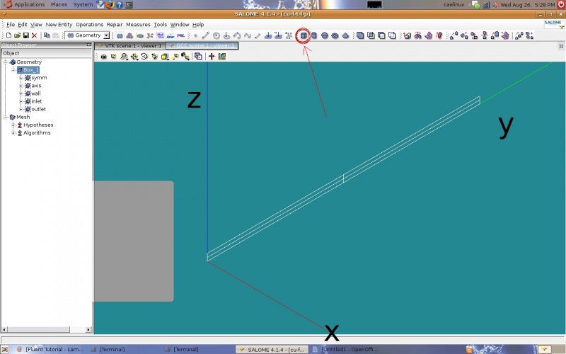
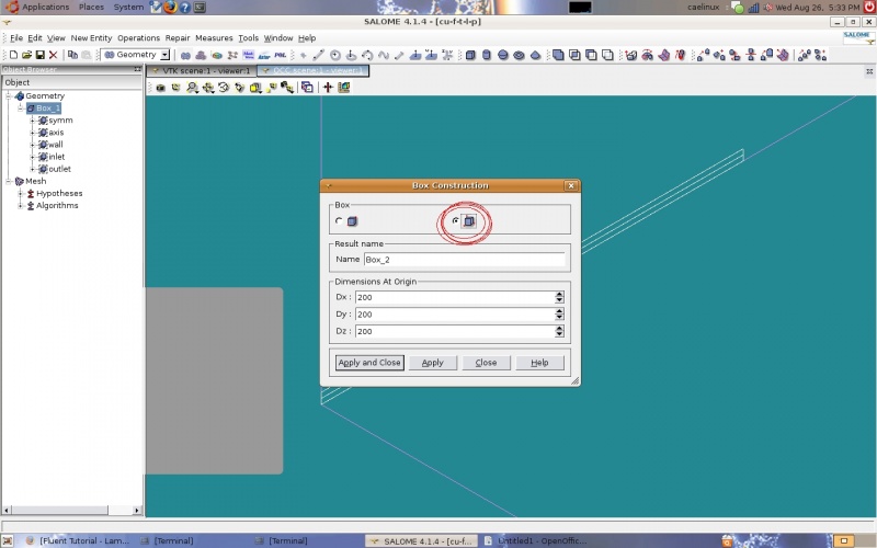
The geometry is a box. The Cornell tutorial uses a 2-D box but Code Saturne can only work with 3-D geometry. The box represents a cross section of a pipe along its length cut in half to take advantage of the flow symmetry around the axis of the pipe. I created a box using the 'create a box' icon which brings up the same dialogue box if one goes to 'New Entity' and then 'Primitives' and then 'Box' in the task bar.
Dx is the width of the box in the x-direction, starting at the origin. My dimensions: Dx=0.001, Dy=8, and Dz=0.1 Units are meters. The next step is to create the groups of faces for boundary conditions. As in the Cornell tutorial, half the pipe is studied to take advantage of symmetry. There are three symmetry B.C.s, one inlet B.C., one outlet B.C., and a wall B.C.
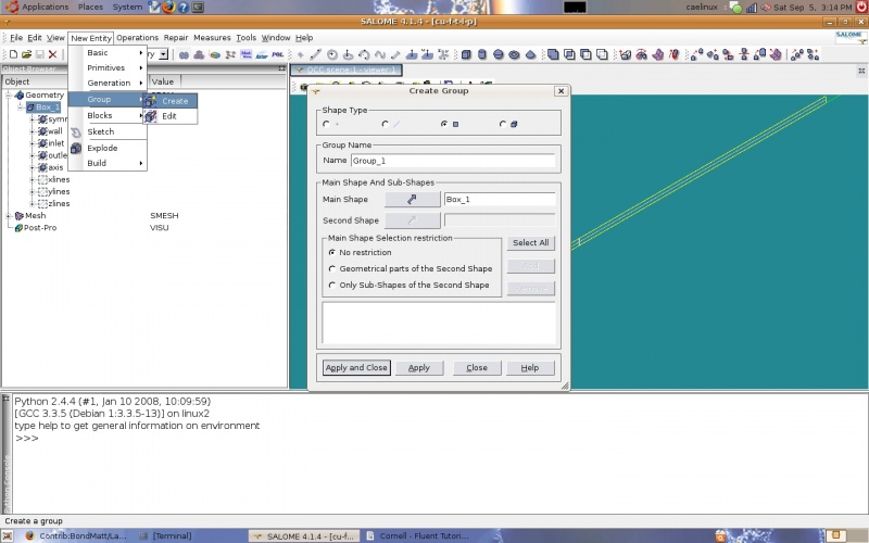
Groups can be created by going to 'New Entity', 'Group', and then 'Create'. When creating a group the elements are selected by type (points, lines, planes, solids) and added with the 'add' button. Descriptive group names should be used to make applying B.C.s easier. Once all elements for a group are selected and the name is specified the 'Apply' button is clicked.
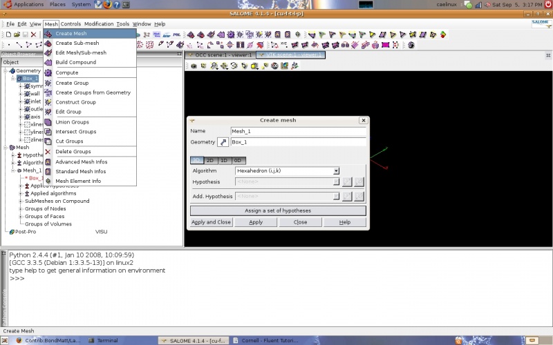
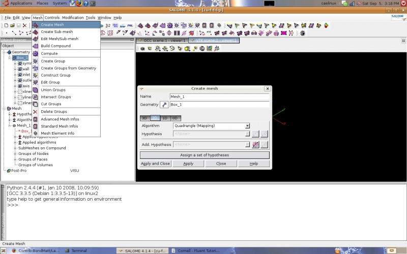
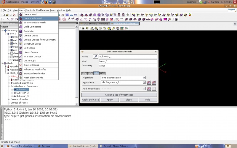
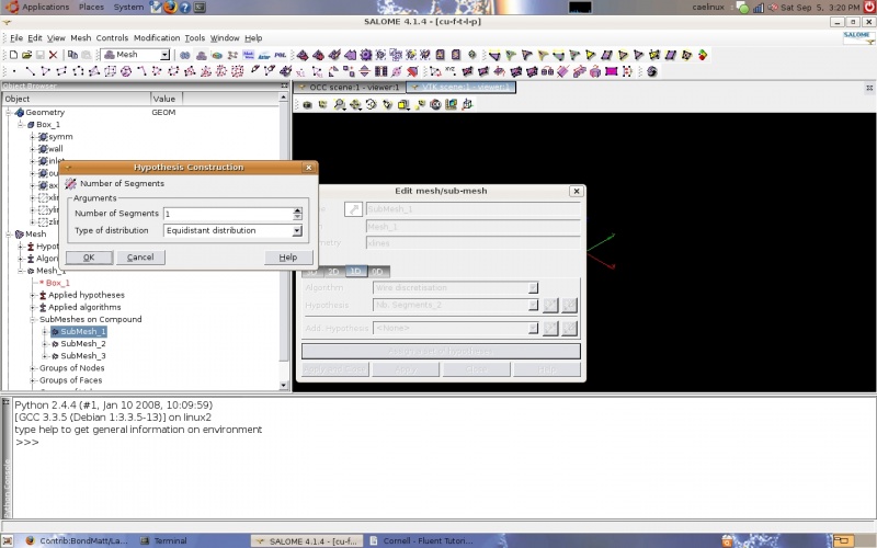
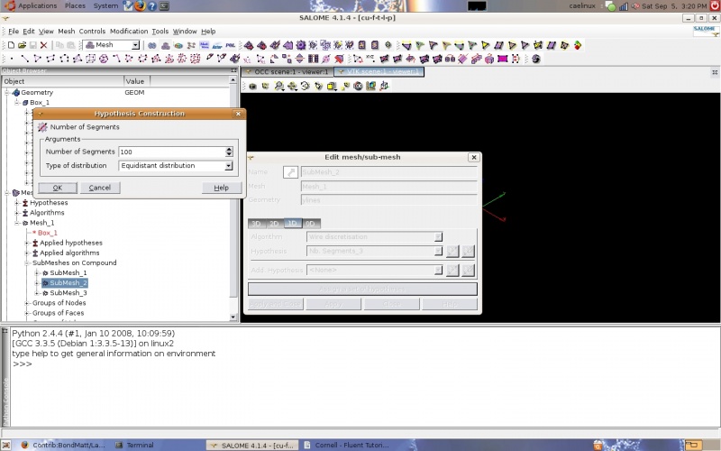
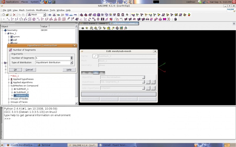
Groups of edges were also created by direction so that the same mesh that is used in the Cornell tutorials could be created. In other words lines running in the x-direction were grouped into a group named 'xlines' and so on. This allows one dimensional submeshes to be created with the number of intervals on the edges specified. These submeshes are 1-dimensional and use the 'wire discretization' algorithm with the 'Nb. Segments' (number of segments) hypothesis. The main mesh used the 'Hexahedron' algorithm (3D) and 'Quadrangle (Mapping)' algorithm (2D). For the main mesh no 1D algorithm is specified since all edges are discretized by the submeshes.
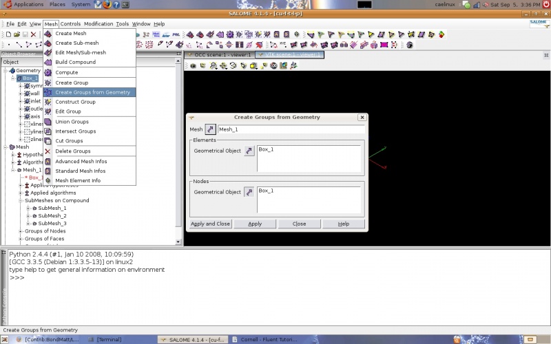
The geometry groups are used to create groups of nodes. One method is to go to 'Mesh' and then 'Create Groups from Geometry' in the taskbar. The mesh and the geometry group are selected and the 'Apply' button selected.
Solver - Code Saturne
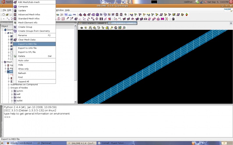
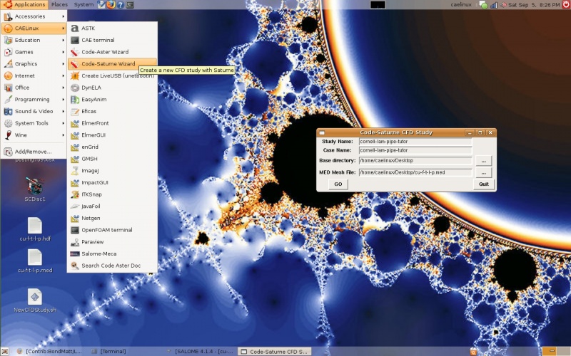
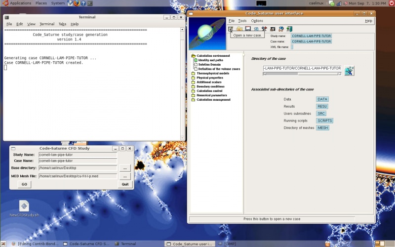
The CFD study was started by launching the 'Code-Saturne-Wizard' and creating a case. This dialogue box can be used to remember/select the right type of mesh to export (MED). To export the mesh it is just a matter of going back to Salome and right clicking on the mesh in the tree and selecting 'Export to MED file'.
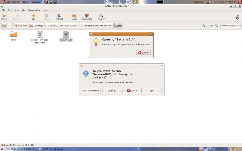
The GUI will launch and directories will be created. I specified that the directories should be created on the desktop but they can be anywhere. The next step is to create a new case. There is an icon provided in the task bar for this in the form of a piece of paper with a pencil. A new case could also be created by going to 'File' and then 'New file'. On the left hand side of the GUI window is a series of folders and files. Each file corresponds to an aspect of the solver including boundary conditions, output file type, fluid properties, and number of iterations, just to name a few. If you should decide to close the Saturne GUI it can be started by opening the directory that was created with the CAELinux wizard and opening the DATA folder. In this folder is a file entitled 'SatuneGUI'. If you double click it and select the 'run in terminal' option from the dialogue box that comes up, the Saturne GUI will appear. You will need to open the .xml file that was saved the last time you were working on that case. As with most computer based work saving often is always a good idea.
I follow the folders from top to bottom going through each file. The first folder is 'Calculation environment' and the first file is 'Identity and paths'. I do not edit anything here. The next file is 'Solution domain'. There are several tabs for this file but the first and last are the only significant ones for this problem. In the 'meshes' tab you should confirm that your mesh is listed. Under the 'stand-alone running' tab the output file type is selected. I used the Ensight Gold format which is compatible with Paraview. I have been unable to get results with the MED format which is compatible with the post processor in Salome. The simulation appears to run just fine but there are no result files created. The next file is 'Definition of volume zones'. I did not edit anything in this file.
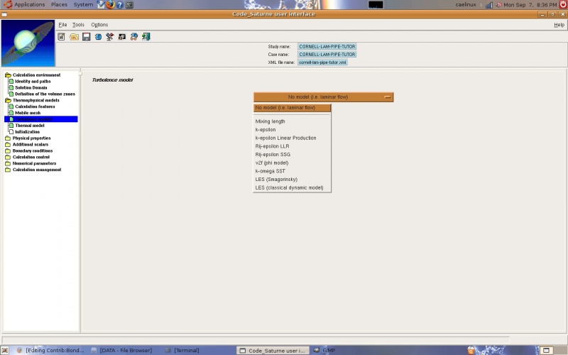
The next folder is 'Thermophysical models'. In the first file ('Calculation features') the flow type must be changed to 'steady flow'. This indicates that the flow does not change at each point with respect to time, ie. the velocity is constant at each point with respect to time. I did not edit the next file ('Mobile mesh'). The next file is 'Turbulence models'. 'No model (ie. laminar flow)' is selected for this problem.
