Difference between revisions of "Contrib:BondMatt/LaminarPipeFlow"
| Line 14: | Line 14: | ||
<br/><br/>[[Image:box.jpg|800x500px]] | <br/><br/>[[Image:box.jpg|800x500px]] | ||
<br/>Dx is the width of the box in the x-direction, starting at the origin. My dimensions: Dx=0.001, Dy=8, and Dz=0.1 Units are meters. The next step is to create the groups of faces for boundary conditions. As in the Cornell tutorial, half the pipe is studied to take advantage of symmetry. There are three symmetry B.C.s, one inlet B.C., one outlet B.C., and a wall B.C. | <br/>Dx is the width of the box in the x-direction, starting at the origin. My dimensions: Dx=0.001, Dy=8, and Dz=0.1 Units are meters. The next step is to create the groups of faces for boundary conditions. As in the Cornell tutorial, half the pipe is studied to take advantage of symmetry. There are three symmetry B.C.s, one inlet B.C., one outlet B.C., and a wall B.C. | ||
| − | <br/><br/>[[Image:box2.jpg]] | + | <br/><br/>[[Image:box2.jpg|800x500px]] |
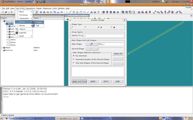
<br/><br/>Groups can be created by going to 'New Entity', 'Group', and then 'Create'. When creating a group the elements are selected by type (points, lines, planes, solids) and added with the 'add' button. Descriptive group names should be used to make applying B.C.s easier. Once all elements for a group are selected and the name is specified the 'Apply' button is clicked. | <br/><br/>Groups can be created by going to 'New Entity', 'Group', and then 'Create'. When creating a group the elements are selected by type (points, lines, planes, solids) and added with the 'add' button. Descriptive group names should be used to make applying B.C.s easier. Once all elements for a group are selected and the name is specified the 'Apply' button is clicked. | ||
| − | <br/><br/>[[Image:groups.jpg]] | + | <br/><br/>[[Image:groups.jpg|800x500px]] |
<br/><br/>Groups of edges were also created by direction so that the same mesh that is used in the Cornell tutorials could be created. In other words lines running in the x-direction were grouped into a group named 'xlines' and so on. This allows one dimensional submeshes to be created with the number of intervals on the edges specified. These submeshes are 1-dimensional and use the 'wire discretization' algorithm with the 'Nb. Segments' (number of segments) hypothesis. The main mesh used the 'Hexahedron' algorithm (3D) and 'Quadrangle (Mapping)' algorithm (2D). For the main mesh no 1D algorithm is specified since all edges are discretized by the submeshes. | <br/><br/>Groups of edges were also created by direction so that the same mesh that is used in the Cornell tutorials could be created. In other words lines running in the x-direction were grouped into a group named 'xlines' and so on. This allows one dimensional submeshes to be created with the number of intervals on the edges specified. These submeshes are 1-dimensional and use the 'wire discretization' algorithm with the 'Nb. Segments' (number of segments) hypothesis. The main mesh used the 'Hexahedron' algorithm (3D) and 'Quadrangle (Mapping)' algorithm (2D). For the main mesh no 1D algorithm is specified since all edges are discretized by the submeshes. | ||
| − | <br/><br/>[[Image:mesh1-3D.jpg]] | + | <br/><br/>[[Image:mesh1-3D.jpg|800x500px]] |
| − | <br/><br/>[[Image:mesh1-2D.jpg]] | + | <br/><br/>[[Image:mesh1-2D.jpg|800x500px]] |
| − | <br/><br/>[[Image:mesh1-submesh1.jpg]] | + | <br/><br/>[[Image:mesh1-submesh1.jpg|800x500px]] |
| − | <br/><br/>[[Image:mesh1-submesh1-hypothesis.jpg]] | + | <br/><br/>[[Image:mesh1-submesh1-hypothesis.jpg|800x500px]] |
| − | <br/><br/>[[Image:mesh1-submesh2-hypothesis.jpg]] | + | <br/><br/>[[Image:mesh1-submesh2-hypothesis.jpg|800x500px]] |
| − | <br/><br/>[[Image:mesh1-submesh3-hypothesis.jpg]] | + | <br/><br/>[[Image:mesh1-submesh3-hypothesis.jpg|800x500px]] |
<br/><br/>The geometry groups are used to create groups of nodes. One method is to go to 'Mesh' and then 'Create Groups from Geometry' in the taskbar. The mesh and the geometry group are selected and the 'Apply' button selected. | <br/><br/>The geometry groups are used to create groups of nodes. One method is to go to 'Mesh' and then 'Create Groups from Geometry' in the taskbar. The mesh and the geometry group are selected and the 'Apply' button selected. | ||
| − | <br/><br/>[[Image:mesh-groups.jpg]] | + | <br/><br/>[[Image:mesh-groups.jpg|800x500px]] |
<br/><br/><br/> '''Solver - Code Saturne''' | <br/><br/><br/> '''Solver - Code Saturne''' | ||
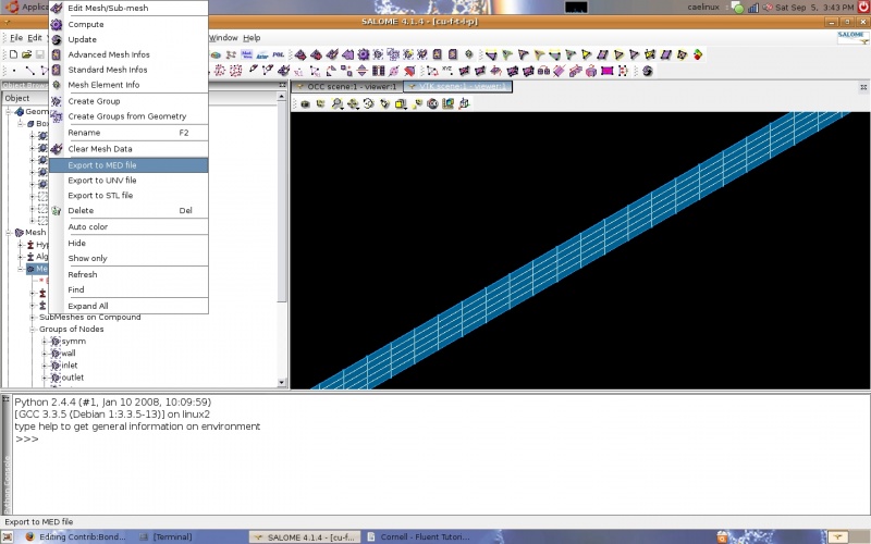
<br/> The CFD study was started by launching the 'Code-Saturne-Wizard' and creating a case. This dialogue box can be used to remember/select the right type of mesh to export (MED). To export the mesh it is just a matter of going back to Salome and right clicking on the mesh in the tree and selecting 'Export to MED file'. | <br/> The CFD study was started by launching the 'Code-Saturne-Wizard' and creating a case. This dialogue box can be used to remember/select the right type of mesh to export (MED). To export the mesh it is just a matter of going back to Salome and right clicking on the mesh in the tree and selecting 'Export to MED file'. | ||
| − | <br/><br/>[[Image:exportMEDmesh.jpg]] | + | <br/><br/>[[Image:exportMEDmesh.jpg|800x500px]] |
Revision as of 20:57, 6 September 2009
Introduction
The problem solved herein is that of a pipe with a uniform velocity field at the inlet and atmospheric pressure at the outlet. The pipe is sufficiently long that the viscous boundary layer is completely formed. A thin slice along the length of the pipe is studied to minimize the time to solve. The inlet velocity is very low (1 m/s) to ensure that flow is laminar. The medium is air and the diameter of the pipe is 0.2m. The Reynolds number, the ratio of inertial and viscous forces, is approximately 100. This is well below 2300, the Reynolds number magnitude commonly accepted as indicating the start of transition from laminar to turbulent flow. Side note: interesting tidbit: laminar flow can occur at extremely high Reynolds numbers (up to 100,000) if the pipe is very smooth and pipe vibrations are controlled. This problem is taken from a FLUENT tutorial from Cornell University, freely available on their website.
Software Versions:
Ubuntu 8.04 LTS
Salome V4.1.4
Code Saturne V1.4.a (GUI)
Fluent Tutorial
The Cornell University Fluent tutorial can be found here Cornell Tutorial
Geometry / Mesh
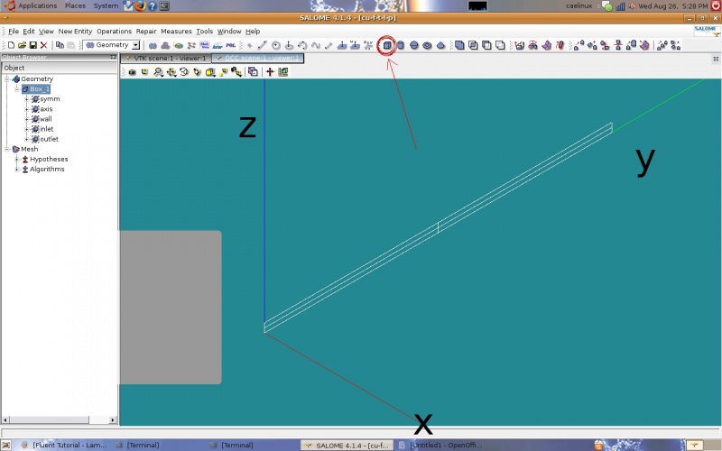
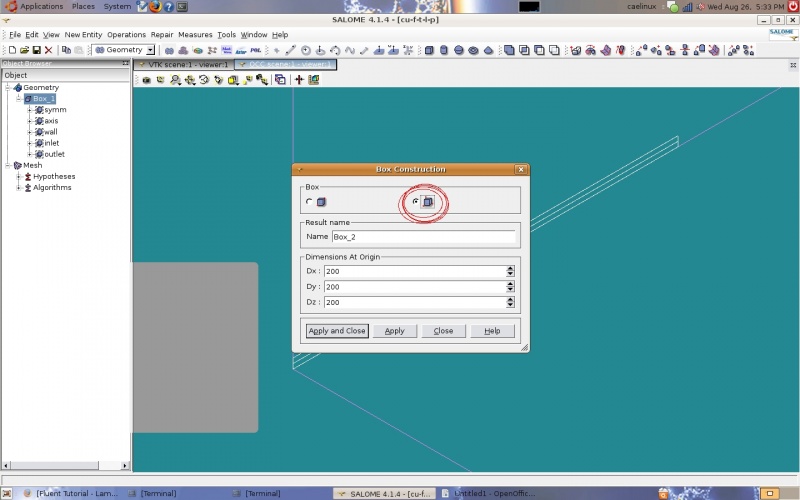
The geometry is a box. The Cornell tutorial uses a 2-D box but Code Saturne can only work with 3-D geometry. The box represents a cross section of a pipe along its length cut in half to take advantage of the flow symmetry around the axis of the pipe. I created a box using the 'create a box' icon which brings up the same dialogue box if one goes to 'New Entity' and then 'Primitives' and then 'Box' in the task bar.
Dx is the width of the box in the x-direction, starting at the origin. My dimensions: Dx=0.001, Dy=8, and Dz=0.1 Units are meters. The next step is to create the groups of faces for boundary conditions. As in the Cornell tutorial, half the pipe is studied to take advantage of symmetry. There are three symmetry B.C.s, one inlet B.C., one outlet B.C., and a wall B.C.
Groups can be created by going to 'New Entity', 'Group', and then 'Create'. When creating a group the elements are selected by type (points, lines, planes, solids) and added with the 'add' button. Descriptive group names should be used to make applying B.C.s easier. Once all elements for a group are selected and the name is specified the 'Apply' button is clicked.
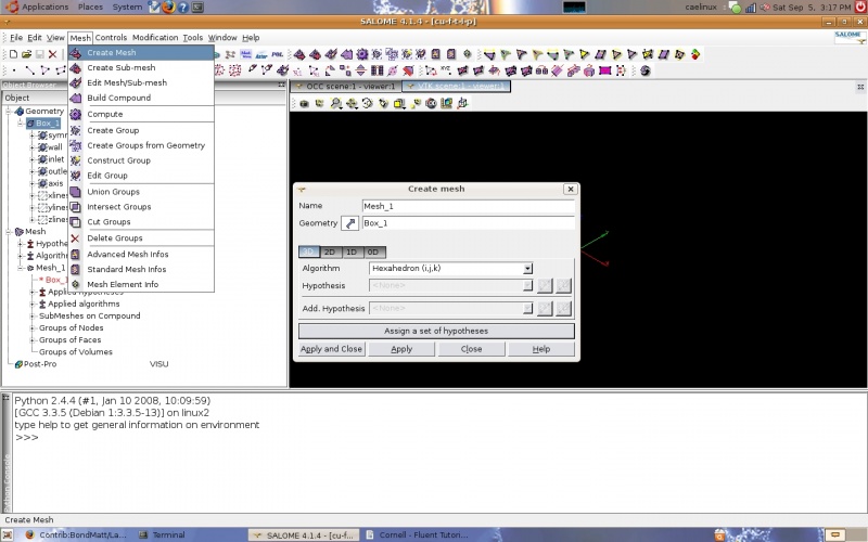
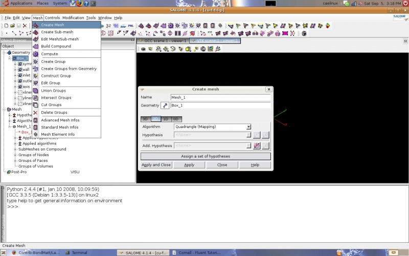
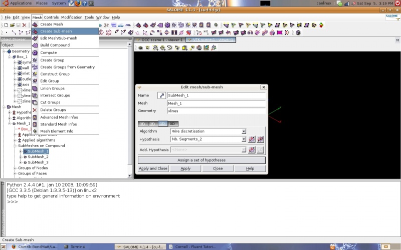
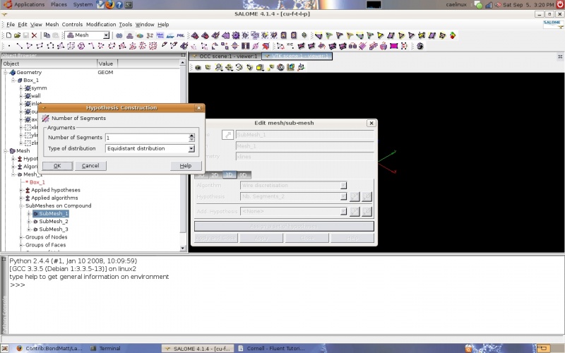
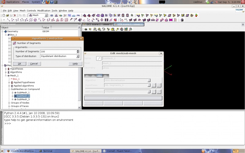
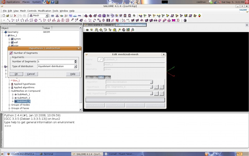
Groups of edges were also created by direction so that the same mesh that is used in the Cornell tutorials could be created. In other words lines running in the x-direction were grouped into a group named 'xlines' and so on. This allows one dimensional submeshes to be created with the number of intervals on the edges specified. These submeshes are 1-dimensional and use the 'wire discretization' algorithm with the 'Nb. Segments' (number of segments) hypothesis. The main mesh used the 'Hexahedron' algorithm (3D) and 'Quadrangle (Mapping)' algorithm (2D). For the main mesh no 1D algorithm is specified since all edges are discretized by the submeshes.
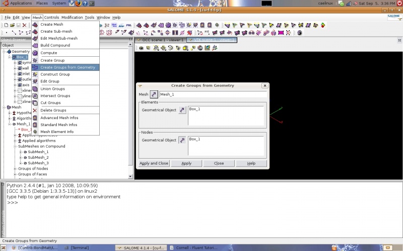
The geometry groups are used to create groups of nodes. One method is to go to 'Mesh' and then 'Create Groups from Geometry' in the taskbar. The mesh and the geometry group are selected and the 'Apply' button selected.
Solver - Code Saturne
The CFD study was started by launching the 'Code-Saturne-Wizard' and creating a case. This dialogue box can be used to remember/select the right type of mesh to export (MED). To export the mesh it is just a matter of going back to Salome and right clicking on the mesh in the tree and selecting 'Export to MED file'.
